Ever seen a technician pull a fuse to shut down a machine, only for the lights to flash or a loud pop to follow?
That reaction is often the result of disconnecting equipment under load without the proper switching device. In industrial environments, moments like this can quickly escalate into equipment damage, unexpected downtime, or even serious injury.
Unsafe isolation practices and improper switching are still major contributors to outages and arc-flash incidents. The underlying issue is simple: many systems continue to rely on outdated or unsafe isolation methods instead of using devices specifically engineered to interrupt electrical loads safely.
This is where load break switches make a meaningful difference. They are widely used across industrial, OEM, municipal, and commercial electrical systems because they offer reliable, safe isolation during maintenance. By interrupting power even when current is flowing, they protect both personnel and equipment from unnecessary risk.
Understanding what a load break switch does and when it should be used is an essential skill for anyone working around power and control systems.
Key Highlights
Load break switches interrupt live current safely using arc-quenching technology, preventing arc-flash incidents, equipment damage, and unsafe fuse-pulling practices.
They provide a visible, lockable isolation point, making maintenance safer and fully compliant with OSHA and NFPA 70E standards.
Prevents unplanned outages, contact failures, and downtime caused by improper disconnect methods or non-load-rated devices.
Used in control panels, motor circuits, commercial facilities, utilities, and renewables for safe shutdowns, partial isolation, and reliable power transitions.
Manual, fused, non-fused, enclosed, transfer, and motor-duty load break switches help match the right protection and performance level to each application.
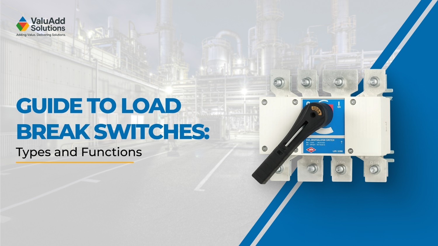
What Is a Load Break Switch?
A load break switch is an electrical switching device designed to safely open or close a circuit while current is flowing. Unlike a simple disconnect switch, a load break switch is built to interrupt electrical load without causing dangerous electrical arcs, ensuring safe operation even under normal current levels.
Why Load Break Switches Are Needed
Load break switches play a critical safety and reliability role in both industrial and commercial electrical systems:
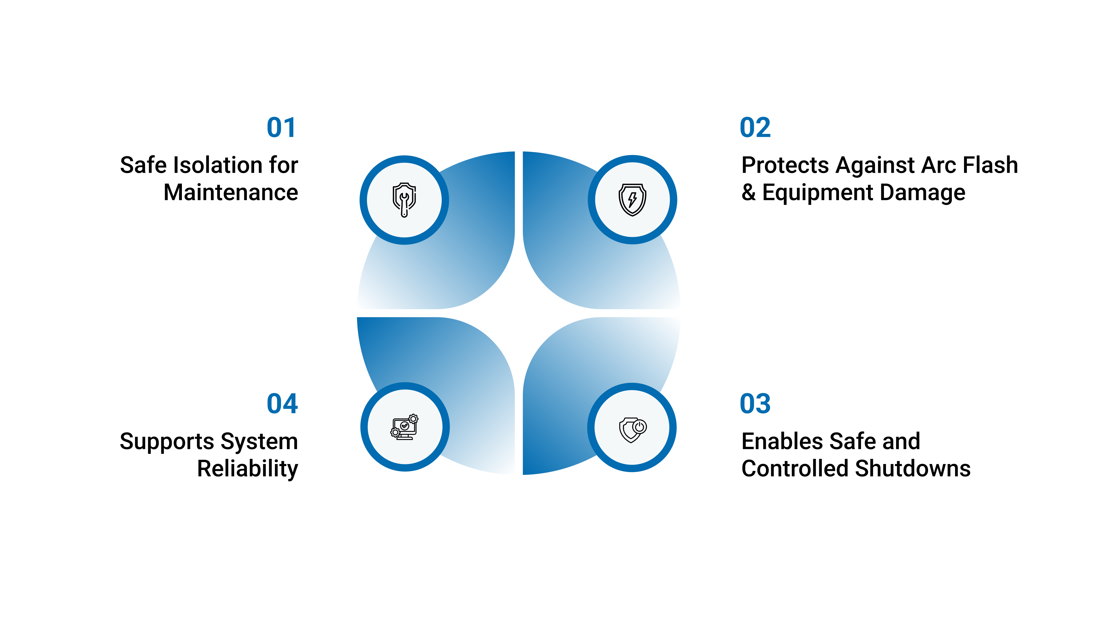
1. Safe Isolation for Maintenance
They allow technicians to completely and visibly isolate equipment before performing repairs or servicing, an essential part of lockout/tagout (LOTO) safety procedures.
2. Protects Against Arc Flash & Equipment Damage
When electrical circuits carrying current are disconnected improperly, large electrical arcs can form. A load break switch is engineered with arc-quenching mechanisms (such as air, gas, vacuum, or spring-powered arc chutes) to extinguish the arc during switching safely.
3. Enables Safe and Controlled Shutdowns
Instead of pulling fuses, unplugging equipment, or opening panels, which is hazardous and not permitted in many codes, the load break switch provides a designed and code-compliant method for safely interrupting power.
4. Supports System Reliability
Helps avoid:
Equipment failure from uncontrolled disconnects
Worker injury and arc-flash exposure
Downtime caused by unsafe switching procedures
Where Load Break Switches Are Commonly Used
Load break switches appear in a wide range of electrical systems where safe shutdown, maintenance access, and circuit isolation are required. They are commonly installed at key points in power distribution networks and industrial equipment control systems.
Industrial Control Panels & MCC Systems
Used to isolate sections of a control panel or motor control center without shutting down the entire facility. Technicians can safely work on one machine or panel section while the rest of the plant continues running. LBS devices are often mounted at panel entry points or upstream of major equipment loads.
Motor Circuits and Process Equipment
Ideal for safely disconnecting motors, pumps, conveyor systems, compressors, and production machinery. Operators can stop equipment under load, avoiding downtime caused by emergency shutdowns and ensuring compliance with NFPA 70E and OSHA LOTO requirements.
Commercial & Institutional Electrical Rooms
Found in schools, hospitals, data centers, airports, and large buildings to provide local disconnect capability for maintenance and emergency switching. They support critical facility uptime by allowing partial system isolation and help protect sensitive equipment from electrical stress.
Utility & Municipal Power Distribution
Used in water treatment plants, power distribution cabinets, feeder systems, and outdoor switchgear cabinets. They help utilities switch between power sources, isolate sections of distribution lines, or perform upgrades without disrupting service to customers.
Renewables, Backup Generators & Transfer Switching
Essential for switching between grid power, solar arrays, battery storage, and generator sources. Load break switches allow safe system transitions without arc hazards, supporting:
Solar combiner boxes and inverter maintenance
Generator load isolation and bypass switching
Automatic and manual transfer switch applications
How Load Breaking Works
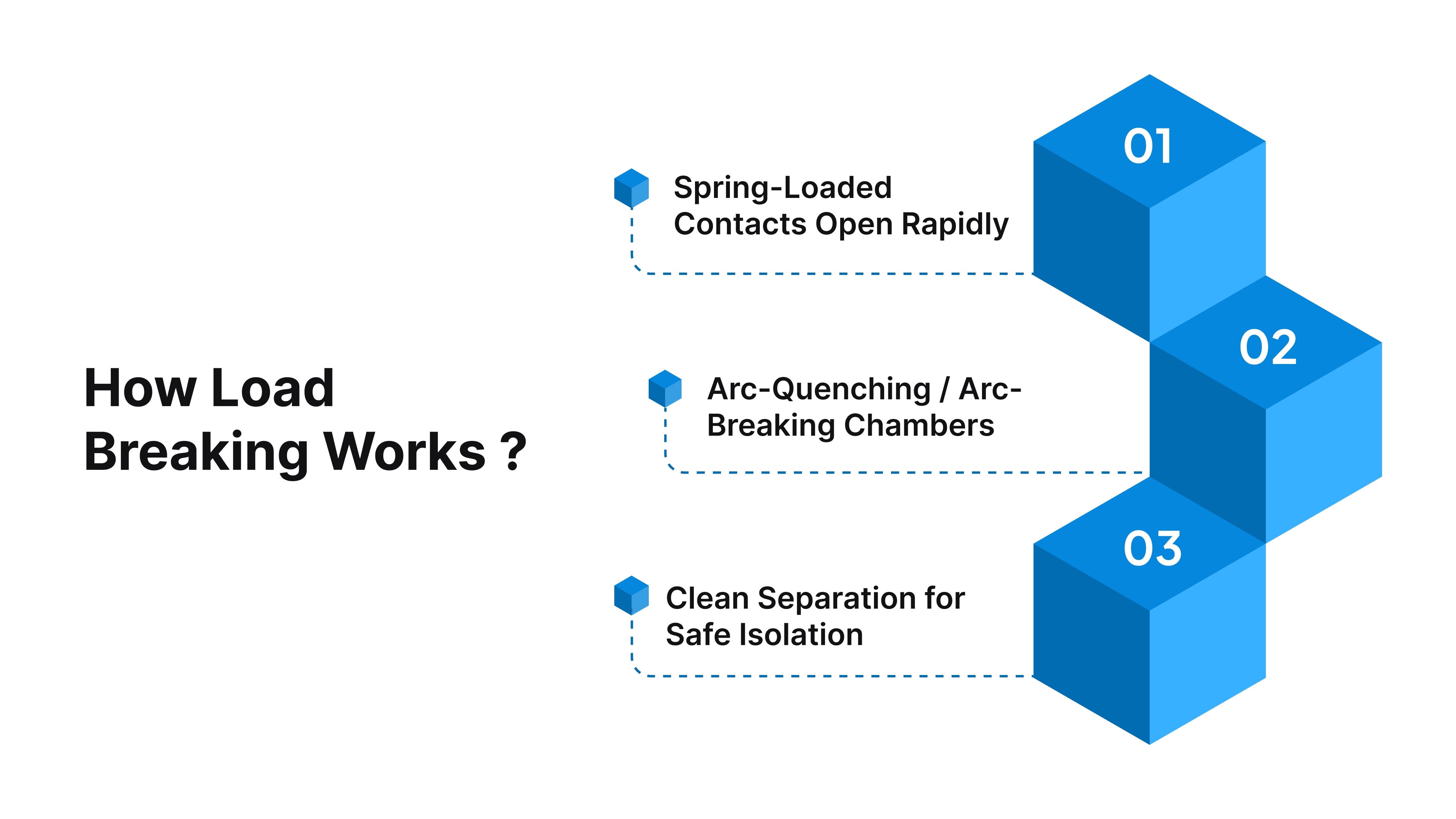
A load break switch is engineered to interrupt electrical current safely by controlling and extinguishing the electrical arc that forms when a circuit is opened under load. Even people without an electrical background can understand the process by looking at the way the internal components manage energy during switching.
Step-by-Step Overview of Internal Operation
When a load break switch is operated while current is flowing, several internal mechanisms work together to break the circuit safely:
1. Spring-Loaded Contacts Open Rapidly
Inside the switch are electrical contacts that normally carry current. When the switch handle is turned:
A spring-loaded mechanism releases energy instantly
The contacts snap apart at high speed
This fast movement prevents the arc from sustaining itself
This is different from a slow, hand-operated separation, which would allow a dangerous arc to continue burning.
2. Arc-Quenching / Arc-Breaking Chambers
When the contacts separate, a temporary electrical arc forms between them. Load break switches include specially engineered arc-control systems such as:
Arc chute chambers
Magnetic blow-out devices
Air, gas, vacuum, or SF₆ insulation
Ceramic or insulated barriers
These components stretch, cool, divide, and extinguish the arc, stopping the current safely and preventing equipment damage.
3. Clean Separation for Safe Isolation
Once the arc is extinguished, the contacts are fully open, meaning:
The circuit is completely isolated
Technicians have visible confirmation of disconnection
Maintenance work can begin safely
This makes load break switches essential for lockout/tagout (LOTO) and compliance with NFPA 70E and OSHA standards.
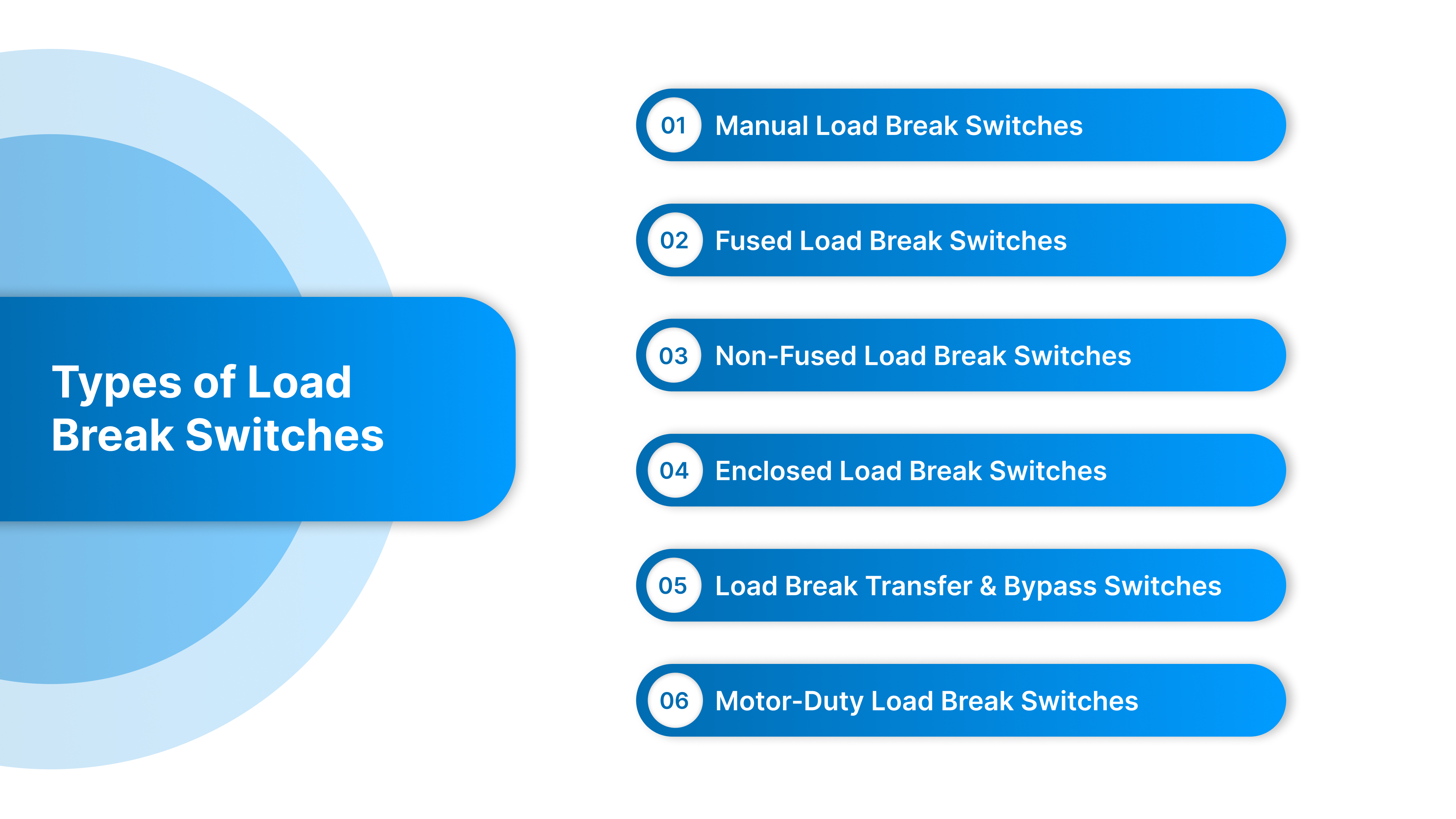
Types of Load Break Switches & Typical Applications
Load break switches are engineered in different configurations to meet varied electrical, environmental, and operational requirements. Understanding the differences helps ensure correct selection, safe operation, and maximum system reliability.
1. Manual Load Break Switches
Manual load break switches are the most common type and are used where an operator needs to open or close a circuit with full control physically. They provide a visible and verifiable means of disconnect, making them ideal for maintenance isolation and lockout/tagout.
Where They’re Used
Industrial control panels and MCC buckets
On-machine disconnect points for individual motors or equipment
Manufacturing lines where equipment must be isolated without stopping production
They offer mechanical interlocks, door interlock safety, padlocking features, and visible blade indication, critical for complying with NFPA 70E and reducing arc-flash exposure during maintenance.
2. Fused Load Break Switches
These switches integrate both switching and overcurrent protection in the same device, making them essential in applications exposed to high fault energy or where circuit protection is required locally.
Where They’re Used
Motor feeders and HVAC units
Transformer and lighting distribution equipment
High-energy industrial and commercial power systems
By combining fuses with switching capability, they eliminate the need for separate protective devices, simplify wiring, minimize panel space, and provide high short-circuit withstand ratings, important for industrial fault levels.
3. Non-Fused Load Break Switches
Non-fused versions are used when overcurrent protection already exists upstream, such as a breaker or fusible switch at a higher level in the system.
Where They’re Used
OEM machinery and packaged systems
Standardized UL508A control panels
Isolating sub-circuits without adding additional protection devices
They reduce cost, footprint, and component complexity, allowing panel builders and OEMs to standardize equipment designs while still maintaining safe and code-compliant disconnect points.
4. Enclosed Load Break Switches
These switches are packaged in rugged enclosures designed to withstand environmental hazards such as moisture, dust, chemicals, and outdoor conditions.
Where They’re Used
Wastewater treatment plants and municipal pump stations
Food & beverage washdown lines and corrosive processing areas
Outdoor industrial switchgear and utility distribution cabinets
Enclosed switches are available in NEMA 4X stainless steel, fiberglass, and polycarbonate housings, offering long-term durability and preventing premature failures caused by condensation, corrosion, and temperature cycling.
5. Load Break Transfer & Bypass Switches
Used in applications where power cannot be interrupted, these switches allow safe transition between power sources such as grid power, generators, solar inverters, or battery storage.
Where They’re Used
Hospitals, data centers, emergency systems
Renewable solar and microgrid installations
Facilities requiring generator or UPS switching
They maintain operation and prevent downtime by switching seamlessly between live sources, protecting critical loads and improving resilience.
6. Motor-Duty Load Break Switches
These are specially engineered for inductive loads with high inrush currents and switching frequency demands.
Where They’re Used
VFD-driven motors, conveyors, compressors, pumps, and mixers
Motor circuits in manufacturing and process automation
They prevent contact erosion and deliver reliable operation in AC-23 utilization category environments, where standard switches would wear out prematurely.
Why Use a Load Break Switch Instead of Pulling Fuses or Using the Wrong Disconnect
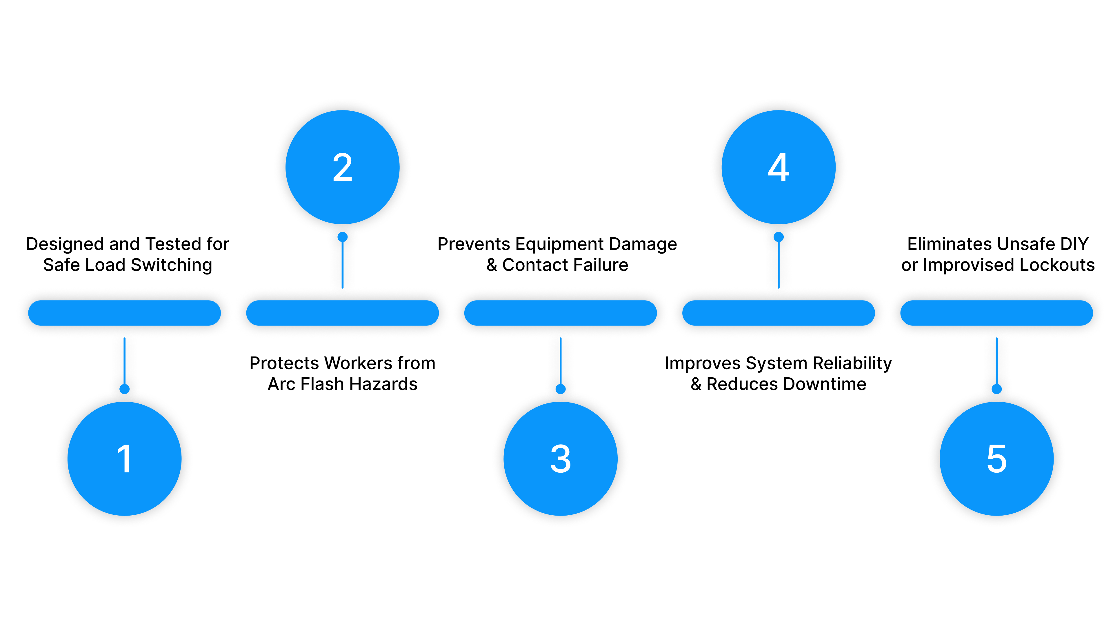
In many industrial and commercial environments, operators have historically disconnected equipment by pulling fuses, opening panels, or using non-load-rated disconnect switches. While these approaches may appear to work, they create serious safety hazards and reliability issues
Designed and Tested for Safe Load Switching
Load break switches are purpose-built for switching energized circuits, equipped with:
Arc-quenching chambers and fast mechanical contacts
Spring-loaded opening mechanisms
Heat and electromagnetic arc-control technology
This ensures a controlled interruption even at high currents, preventing the violent arc events that occur during unsafe switching.
Protects Workers from Arc Flash Hazards
Pulling fuses or opening a non-load-rated disconnect while current is flowing can trigger dangerous arc flash events, releasing explosive heat, pressure, and molten metal.
Using a load break switch:
Minimizes arc flash exposure at the switch location
Supports safe lockout/tagout procedures
Meets compliance requirements under OSHA, NFPA 70E, and NEC
Arc flash prevention isn’t optional, it’s a legal and operational necessity.
Prevents Equipment Damage & Contact Failure
Improper load switching can lead to:
Welded contacts
Destroyed fuse holders
Melted components
Nuisance shutdowns and costly replacement
Load break switches maintain clean mechanical separation, ensuring equipment isn’t destroyed during normal isolation procedures.
Improves System Reliability & Reduces Downtime
In industrial and OEM environments, an uncontrolled shutdown can cost thousands per minute. Unsafe switching methods often cause:
Unexpected outages
Restart complications
Production or process disruption
A load break switch enables planned isolation without powering down entire lines or systems.
Eliminates Unsafe DIY or Improvised Lockouts
Improper locking and tagging (such as padlocking fuse pulls or breaker handles) is a leading cause of electrical safety incidents.
Load break switches provide:
Visible open gap verification
Padlock-ready handle interlocking
Confidence that the equipment is truly de-energized before servicing
A load break switch is the correct, engineered, and code-compliant solution for safe circuit isolation.
Where a Load Break Switch Sits Inside a Control Panel
A load break switch is installed upstream of the equipment being isolated, after the main feeder protection and before motor starters, VFDs, or other components. It provides a local, visible, and safe isolation point for service and lockout/tagout.
Typical Electrical Path Placement
Below is a simplified text-based diagram commonly used for training, showing where the load break switch fits in a standard motor or process equipment control panel:
Incoming Power ─── Main Breaker ─── Load Break Switch ─── Contactor / VFD ─── Motor / Load
Main Breaker protects against short circuits and overload conditions.
Load Break Switch provides safe switching under load and isolation for maintenance.
Contactor/VFD controls motor operation or process automation.
Motor / Process Load is the equipment being driven.
Example Panel Layout (Door-Mounted Handle Orientation)
[Main Enclosure Door]
├─ Main Breaker (through-door operator optional)
├─ Load Break Switch (handle through the door for LOTO)
├─ Fuse Block / MCCB / VFD
└─ Control Components (PLC, Terminal Blocks, Relays, etc.)
Allows operators to disconnect equipment without opening the panel.
Reduces exposure to energized parts per NFPA 70E requirements.
Enables locked-out safe position externally, without accessing the enclosure interior.
How Technicians Interact With the Load Break Switch During LOTO
To safely work on equipment, maintenance personnel must verify that the system is fully de-energized. A load break switch simplifies and standardizes this process:
Typical lockout/tagout workflow
Turn the handle to OFF (opening contacts and extinguishing the arc safely)
Verify visible blade position or viewing window confirmation
Apply a padlock through the handle’s lockout hasp provision
Tag the device with a maintenance identifier
Attempt a restart to verify the system is disabled (try-start testing)
This process eliminates unsafe alternatives such as:
Pulling fuses by hand
Opening energized cabinets
Using breakers as isolation devices
Why Placement Inside the Panel Matters
Correct installation provides:
Shorter downtime by isolating individual equipment rather than entire systems
Predictable maintenance access, reducing arc-flash boundaries
Repeatable safety process across standardized control panel designs
Cleaner wiring and panel layout, aiding panel builders and technicians
In OEM and industrial environments, standardized placement of load break switches dramatically improves the ability to service equipment quickly and safely.
5 Common Mistakes, Failures & Troubleshooting Tips
Even properly engineered load break switches can fail prematurely if installed incorrectly, sized improperly, or used outside their intended purpose.
1. Overheating
Excessive heat can lead to insulation breakdown, contact damage, and ultimately catastrophic failure.
Typical Causes
Loose terminals or insufficient torque during installation.
Undersized conductors or switches incorrectly rated for the load.
Excessive switching frequency beyond design limits.
How to Prevent It
Perform routine torque checks as part of scheduled preventive maintenance (PM)
Verify conductor size and thermal rating match load current.
Select switches specifically designed for repetitive duty or motor-duty loads.
2. Worn or Loose Operating Handles
Load break switch handles experience mechanical wear from repeated operation, especially in high-usage industrial environments.
Typical Causes
Excessive force was applied by operators
Misaligned linkage mechanisms
Aging of mechanical components
How to Prevent It
Inspect the handle and linkage periodically for free movement and alignment
Replace handle kits whenever looseness is observed
Consider switches with reinforced handle mechanisms for heavy-duty use cases
3. Improper Mounting Location
Environmental placement issues can significantly affect switch life and performance.
Typical Causes
Installed too close to heat-generating equipment such as VFDs or transformers
High vibration or shock exposure.
Poor air circulation inside the enclosure
How to Prevent It
Follow manufacturer clearance guidelines for heat and ventilation spacing.
Use vibration-resistant mounting hardware in industrial or mobile applications.
Consider enclosed / NEMA 4X / stainless housings in harsh or corrosive environments.
4. Loose Terminals & Conductor Movement
Thermal cycling and machinery vibration can cause terminals to loosen over time if not properly maintained.
Typical Causes
Temperature fluctuations during equipment start/stop cycles.
Nearby mechanical equipment is causing vibration.
How to Prevent It
Include torque checks in scheduled preventive maintenance plans
Use lock-washer or spring pressure terminals where recommendedFollow torque specification labels and do not rely on “hand feel.”
5. Using a Non-Load-Rated Device for Load Switching
One of the most dangerous field mistakes is using a disconnect, breaker, or fuse puller for switching loads when they are not designed for arc interruption.
Typical Causes
Incorrect component selection.
Misunderstanding of the differences between switches, breakers, and isolators.
How to Prevent It
Verify the switch is load-break rated (AC-22 / AC-23 duty category)
Confirm short-circuit and utilization category specifications for the application.
Train technicians on the differences between isolation and switching.
Most load break switch issues are preventable through correct equipment selection, proper installation, and consistent preventive maintenance.
How ValuAdd Supports Smarter Load Break Switch Decisions
Selecting a load break switch isn’t just an engineering box to check; it directly impacts safety, uptime, and long-term system performance.
Here’s how Valuadd help customers make better decisions that reduce risk and improve reliability across OEM equipment, control panels, and industrial facilities
Application & Engineering Guidance
ValueAdd helps customers apply load break switch knowledge correctly in real systems by offering support with:
Selecting proper voltage, current, utilization category (AC-21/22/23), and SCCR ratings
Determining when fused vs non-fused configurations are appropriate
Evaluating enclosure needs for indoor, outdoor, washdown, or corrosive environments
Optimizing handle placement and interlocking for OSHA-compliant lockout/tagout
Correct specification prevents overheating, arc-flash risk, and premature failure.
Local Availability & Standardization Support
Serving NC, SC & VA, ValueAdd works with regional distribution to ensure:
Reliable stocking for fast access and reduced downtime
Smooth repeatability for OEM production builds
Cleaner panel designs and simplified BOM standardization
Reduces lead-time issues and supports scalable equipment manufacturing.
Safety & Compliance Alignment
We guide teams through standards that directly affect load break switch selection and placement, including:
NFPA 70E electrical safety & arc-flash boundaries
OSHA lockout/tagout isolation verification
UL508A panel builder requirements
NEC installation considerations
Safety compliance prevents incidents and protects teams doing live maintenance work.
Choosing the right load break switch and installing it correctly enhances electrical safety, reduces arc-flash risk, boosts equipment uptime, and protects production. It also extends component life and helps lower long-term maintenance costs.
Conclusion
Load break switches are essential for safe and reliable electrical system operation. When correctly specified and integrated, they reduce arc-flash risk, improve maintenance safety, prevent costly downtime, and support OSHA-compliant lockout/tagout practices. With higher performance demands and tighter safety standards, choosing the right switch, and applying it correctly has become more critical than ever.
ValueAdd supports OEMs, panel shops, distributors, and industrial plants across North Carolina, South Carolina, and Virginia with practical application guidance, engineering support, and local availability to ensure smarter selection and long-term reliability. Reach out to ValueAdd for application support or product guidance.
Frequently Asked Questions
1. What is the main purpose of a load break switch?
A load break switch allows electrical circuits to be safely disconnected while current is still flowing, using arc-quenching technology to prevent dangerous arc-flash events and equipment damage.
2. How is a load break switch different from a standard disconnect?
A standard disconnect is designed for isolation only when the load is not energized, whereas a load break switch is engineered to interrupt live current safely under load conditions.
3. Can a circuit breaker replace a load break switch?
Not typically. Breakers are for fault protection, not routine switching. Using them for regular load switching causes contact wear and increases failure risk. A load break switch provides safe mechanical isolation.
4. When should a fused load break switch be used instead of a non-fused version?
Use fused models when overcurrent and fault protection are required at the disconnect point. Use non-fused when upstream protection already exists and only isolation is needed.
5. What utilization categories (AC-21, AC-22, AC-23) mean?
These define the type of load the switch can safely interrupt:
AC-21: Resistive loads
AC-22: Mixed load types
AC-23: Motor and highly inductive loads
Choosing the wrong category can result in contact damage.