Introduction
A fault code on a VFD display means one thing in a production environment: the motor has stopped. These drives control pumps, fans, conveyors, and compressors across manufacturing, water treatment, and oil and gas — and when they go down, the whole process follows.
VFD faults are among the most disruptive and frequently misdiagnosed failures in industrial facilities. Most trace back to a predictable set of root causes: power quality issues, environmental conditions, wiring errors, and aging components.
Up to 60% of VFD downtime stems from external factors rather than internal drive failure. That means proper troubleshooting starts outside the drive itself — not with a replacement order.
This guide covers the 8 most common VFD faults — symptoms, root causes, step-by-step fixes, and when to repair vs. replace.
Key Takeaways
- The 8 most common VFD faults: overcurrent, DC bus overvoltage, undervoltage, overheating, ground fault, motor overload, communication errors, and capacitor degradation
- Root causes fall into four categories: electrical, mechanical, environmental, and software/configuration
- Always isolate the root cause first: disconnect the motor and test the drive unloaded to confirm whether the fault is internal or external
- Replace rather than repair when facing repeated thermal events, physical inverter damage, or a drive past its rated service life
- Preventive maintenance eliminates most recurring faults through cleaning, thermal monitoring, and connection checks
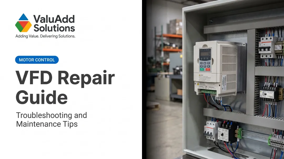
What Is a VFD and How Does It Work?
A Variable Frequency Drive (VFD) controls motor speed by adjusting the frequency and voltage of AC power supplied to an electric motor. This precise control enables significant energy savings — particularly in centrifugal loads like pumps and fans, where power consumption is proportional to the cube of speed.
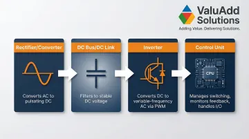
The Four Essential Stages
Every VFD consists of four main stages:
- Rectifier (Converter): Converts incoming fixed-frequency AC power into pulsating DC using a three-phase diode bridge
- DC Bus (DC Link): Filters pulsating DC into smooth, stable DC voltage using capacitor banks and often a DC link choke to reduce harmonics
- Inverter: Uses high-speed IGBT switches to convert DC bus voltage back into variable-frequency AC output via Pulse Width Modulation (PWM)
- Control Unit: Manages IGBT firing, monitors feedback (current, voltage, speed), and handles I/O communication
Knowing which stage is failing shapes every repair decision. In practice, most VFD faults trace back to external factors — installation environment, power quality, motor condition — rather than the drive itself.
8 Most Common VFD Faults: Symptoms and Causes
Most VFD failures display a fault code on the drive's diagnostic display. Always record this code first — it narrows the root cause significantly and guides your troubleshooting process.
The eight faults below cover the most common failure modes — each entry includes symptoms to identify and causes to investigate.
Fault 1: Overcurrent (OC) Fault
Symptoms:
- Drive trips immediately at startup or during acceleration
- "OC" or "Over Current" fault code displayed
- Motor may jerk or fail to rotate
Likely Causes:
- Acceleration ramp set too fast for the load's inertia
- Mechanical binding or seized load (jammed bearings, blocked pump)
- Short circuit in motor wiring or cable damage
- Undersized VFD for the connected load's peak current requirements
Fault 2: DC Bus Overvoltage Fault
Symptoms:
- Drive trips during deceleration or with sudden load changes
- "OV" fault code shown
- May reset on restart but recurs under same conditions
Likely Causes:
- Deceleration ramp set too aggressively for the load's inertia
- High-inertia loads (large fans, centrifuges) acting as generators during rapid deceleration, feeding energy back into the DC bus
- Voltage spikes or surges on the input AC line
- Missing or undersized braking resistor for high-inertia loads
Fault 3: DC Bus Undervoltage / Low Voltage Fault
Symptoms:
- Drive fails to start or drops out unexpectedly
- "UV" or low voltage fault displayed
- May coincide with voltage dips on the supply side
Likely Causes:
- Incoming supply voltage too low or inconsistent (sags, brownouts)
- Loose power connections at input terminals
- Failing pre-charge circuit unable to limit inrush current
- Aging DC bus capacitors losing capacitance, leading to excessive ripple
Fault 4: Overheating / Thermal Fault
Symptoms:
- Drive shuts down after running for a period
- "OH," "OHT," or temperature fault code
- Heatsink or cabinet temperature elevated
- Cooling fan audibly straining or silent
Likely Causes:
- Blocked or failed cooling fans (typical lifespan 3-5 years)
- Clogged heatsink fins from dust or oil mist
- Ambient temperature exceeding drive's rated limit (typically >40°C)
- Improper enclosure ventilation or drive mounted in confined space
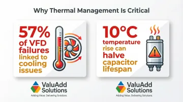
Cooling issues contribute to approximately 57% of VFD failures, and a 10°C temperature increase can halve the life of electrolytic capacitors — making thermal management one of the highest-leverage maintenance priorities.
Fault 5: Ground Fault (Earth Fault)
Symptoms:
- Drive trips at startup or under load
- "GF" or earth fault code displayed
- May be intermittent depending on moisture or vibration
Likely Causes:
- Damaged insulation on motor leads allowing leakage to ground
- Moisture ingress into conduit or motor terminal box
- Poorly secured cable connections creating intermittent contact to ground
- Cable abrasion or cuts in motor leads
Fault 6: Motor Overload Fault
Symptoms:
- Gradual trip after sustained operation at high load
- "OL" or overload fault displayed
- Motor may run warm before trip
Likely Causes:
- Motor operating beyond its rated current (FLA) for extended periods
- Mechanical overload from clogged pumps, jammed conveyors, or bearing wear
- Incorrect motor nameplate data entered into drive parameters
- Process changes increasing load (higher viscosity fluid, increased friction)
Fault 7: Communication / Control Fault
Symptoms:
- Drive displays communication error, parameter fault, or keypad error
- May fail to accept commands from PLC or control panel
- Unexpected behavior after programming changes
Likely Causes:
- Corrupted or factory-reset parameters
- Broken or loose communication cable (RS-485, Ethernet)
- Incorrect baud rate or protocol settings
- Electromagnetic interference (EMI) from nearby power cables corrupting control signals
Fault 8: Capacitor Degradation / DC Bus Fault
Symptoms:
- Erratic DC bus voltage readings
- Increased harmonic distortion
- Drive reports bus faults under normal loads
- Drive age exceeds 7–10 years with no capacitor maintenance
Likely Causes:
- Electrolytic capacitor aging accelerated by high operating temperatures (electrolyte evaporation)
- Extended periods of inactivity causing capacitor deformation
- Ripple current exceeding capacitor ratings over time
- Overvoltage stress from line transients or improper DC bus voltage levels degrading dielectric material
How to Troubleshoot and Fix VFD Faults: Step-by-Step
Applying a fix before isolating the root cause leads to repeat failures and unnecessary part replacement. The process below prevents this.
Step 1: Read the Fault Code and Observe Symptoms
Record the exact fault code from the drive's display or diagnostic log — this is the fastest shortcut to narrowing root cause. Consult the manufacturer's manual for code definitions.
Note the conditions when the fault occurs:
- Startup vs. under load
- After sustained run time
- During deceleration
- With specific load changes
Check for visible symptoms:
- Burning smell or discoloration on components/wiring
- Blocked fans or clogged heatsinks
- Condensation or moisture
- Physical damage to terminals
Step 2: Isolate the Root Cause Category
Disconnect the motor leads and run the VFD unloaded:
- If the fault disappears → issue lies in the motor or cabling
- If it persists → problem is internal to the drive or the incoming supply
Test incoming supply voltage across all three phases with a multimeter. Unbalanced, low, or spiky input causes more VFD faults than most technicians expect — many of which look like internal drive problems at first.
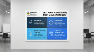
Determine the root cause category:
- Electrical: Wiring, supply quality, voltage issues
- Mechanical: Load-side problems (binding, overload)
- Environmental: Heat, moisture, contamination
- Software/Configuration: Parameter settings, communication
Each category maps to a specific repair path in Step 3.
Step 3: Apply the Correct Fix Based on Root Cause
For Electrical Faults (overcurrent, overvoltage, undervoltage, ground fault):
- Inspect and re-torque all input and output terminal connections
- Test motor insulation resistance with a megohmmeter (minimum 5 MΩ per IEEE 43)
- Replace damaged cabling
- Install surge protection or 3-5% impedance line reactors if voltage spikes confirmed
Mechanical and Load Faults (motor overload, high starting load):
- Manually rotate the connected load to check for binding
- Verify VFD's acceleration and deceleration ramp settings against load's inertia
- Confirm motor nameplate data (FLA, voltage, poles) correctly entered in drive parameters
- Add a braking resistor for high-inertia deceleration loads (resistor must handle average regenerative power)
When the Fault Is Environmental or Thermal (overheating, thermal trips):
- Clean heatsink fins, cooling fans, and air filters with compressed air
- Verify enclosure has adequate ventilation clearance per manufacturer specs
- Check ambient temperature and add supplemental cooling if needed
- For harsh environments, ValuAdd supplies VFDs with IP65, IP66, and IP68-rated enclosures alongside IEEE 519-compliant designs — both of which reduce contamination exposure and harmonic-induced heating faults
For Software/Communication Faults:
- Restore drive to factory defaults (after documenting all current parameters)
- Re-enter correct motor and application parameters
- Check communication cable shielding and grounding
- Verify protocol settings match PLC or SCADA configuration
- Replace communication cable if signal integrity cannot be confirmed
Step 4: Test and Validate the Fix
Run the drive through a full cycle:
- Start, run, and stop under no load first
- Then under normal operating load
- Monitor current, voltage, and temperature readings against expected values
Watch for fault recurrence over at least one full operating shift. A fault that returns within hours indicates the root cause was not fully resolved.
Document everything:
- Fault code
- Root cause identified
- Repair performed
- Date
This log becomes critical for identifying recurring failure patterns and informing future maintenance scheduling.
When Should You Fix vs Replace Your VFD?
The repair-vs-replace decision comes down to three factors: cost of repair relative to replacement, risk of repeat failure, and how critical the drive is to your process. For high-criticality applications — pumps, compressors, continuous production lines — unplanned downtime costs can tip the balance toward replacement even when repair looks cost-effective on paper.
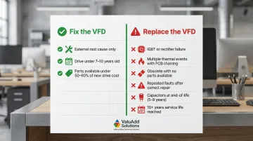
Fix the VFD When:
- The fault is traced to an external cause (wiring, supply, load) with no internal component damage
- The drive is within its expected service life (typically under 7–10 years for low voltage units)
- Replacement parts (capacitors, fans, control boards) are readily available and cost less than 50-60% of a new drive's price
Replace the VFD When:
- The inverter IGBTs or rectifier bridge have failed (repair cost typically approaches new drive cost)
- The drive has experienced multiple thermal events causing PCB discoloration or component charring
- The unit is obsolete with no available spare parts or firmware support
- Repeated faults recur despite correct diagnosis and repair, indicating systemic degradation
- Electrolytic capacitors are approaching end-of-life (typically 5–9 years, depending on operating temperature)
- The facility is upgrading to energy-efficient or IEEE 519-compliant drives to reduce harmonic distortion
- The drive has operated for 10+ years, approaching typical service life for low-voltage units
When repair cost exceeds 50-60% of a new unit's price, factor in your process criticality and lead time for a replacement drive — in some facilities, two weeks of downtime costs more than the drive itself.
Preventive Maintenance to Reduce VFD Faults
The majority of VFD faults are preventable — most originate from conditions a structured maintenance routine would have caught weeks or months earlier. Approximately 60% of VFD failures are preventable through routine maintenance. The checklist below covers the highest-impact maintenance tasks for industrial drives.
Cleaning, Connections, and Insulation Checks
Cleaning schedule:
- Monthly in dirty environments (machining, woodworking, dusty facilities)
- Quarterly in climate-controlled facilities
- Clean cooling fans, heatsink fins, and air filters each time
- Replace cooling fans every 3-5 years as consumable components
Terminal connections: Re-torque all power and control terminals to specification on a scheduled basis. Thermal cycling loosens connections over time — loose connections increase resistance, leading to arcing, overheating, and eventual failure.
Insulation resistance testing: Test motor cables and windings with a megohmmeter (disconnect the VFD first). Minimum acceptable reading is 5 MΩ per IEEE 43 for windings rated under 1 kV. This catches early ground fault conditions before they trip the drive.
Monitoring, Parameters, and Enclosure Selection
Log and trend key metrics including DC bus voltage, operating temperature, and current draw patterns. Gradual shifts in these readings often signal capacitor degradation or cooling performance decline weeks before a catastrophic fault.
Review drive parameters after any system change — motor replacement, load modification, control system update, or process setpoint change. Configuration drift causes recurring faults in facilities without documented parameter backups.
Match enclosure rating to the installation environment:
| Rating | Application | Protection Level |
|---|---|---|
| NEMA 1 / IP20 | Indoor, clean | Touch and falling dirt |
| NEMA 12 / IP54 | Indoor, industrial | Dust and dripping water/oil |
| NEMA 4/4X / IP66 | Washdown, outdoor | Watertight; 4X adds corrosion and ice testing |
When in doubt, specify one enclosure class above the minimum for your environment — the cost difference is minor compared to an unplanned drive replacement.
Frequently Asked Questions
What are common issues that can arise in a VFD system?
The most frequent fault categories are overcurrent, overvoltage, overheating, ground faults, and motor overload. Most trace back to wiring issues, environmental conditions (dust, heat, moisture), or incorrect parameter settings rather than internal drive failure.
How can you tell if a VFD is bad?
Key indicators of a failed drive include fault codes that recur after correct repair attempts, physical signs like burned components or discolored PCBs, inability to hold DC bus voltage, and IGBT failure. Faults caused by external factors (supply, load, or cabling) do not indicate a bad drive.
What causes VFD overcurrent faults?
Main causes include acceleration ramp set too fast for the load's inertia, mechanical binding on driven equipment (seized bearings, jammed conveyors), short circuits in motor wiring, or an undersized drive for the application's peak current requirements.
How often should a VFD be serviced?
At minimum, conduct an annual inspection covering cleaning, connection re-torquing, and parameter verification. Increase frequency to quarterly in harsh or high-duty environments. Inspect capacitors after 5–7 years of service, and replace cooling fans every 3–5 years.
Can a VFD damage a motor?
Yes. Excessive dV/dt from an improperly configured drive stresses winding insulation — a known risk on cable runs over 50–100 feet. NEMA MG1 Part 31 sets peak voltage tolerance at 3.1× rated; incorrect current settings cause thermal damage beyond that threshold. Use output reactors or dV/dt filters on longer runs.
What is the most common VFD fault?
Overcurrent (OC) is the most frequently reported VFD fault in industrial settings, typically caused by improper acceleration settings or mechanical load issues.