Ever connected a 120 V device only to find it instantly failed, with no clear reason why? In many older industrial facilities, the culprit is a High-Leg Delta system. This 3-phase, 4-wire configuration delivers both single-phase and 3-phase power. Still, one phase carries a higher voltage to neutral, typically around 208 V instead of 120 V. Misidentifying that “wild-leg” can lead to costly equipment damage, nuisance trips, or safety hazards.
While High-Leg Delta is less common in modern builds, it remains widespread in legacy plants, rural manufacturing sites, and facilities that haven’t fully converted to newer power systems.
Understanding how to identify, label, and properly assign loads on a High-Leg Delta network isn’t optional; it’s essential for safe wiring, reliable control systems, and keeping production running.
Key Highlights
High-Leg Delta provides both 120 V and 240 V power, but the “wild leg” carries ~208 V to neutral, creating a high miswiring risk.
NEC requires the high leg on Phase B and marked orange to prevent accidental 120 V load connection.
Only A–N and C–N can supply 120 V; the high leg must be used only for 240 V and 3-phase equipment.
Legacy facilities face imbalance and VFD/automation compatibility issues without proper filtering or power correction.
ValuAdd helps ensure safe design with correct components, UL 508A guidance, and reliable upgrades for High-Leg Delta systems.
What Is a High-Leg Delta System?
A High-Leg Delta system (also known as wild-leg, stinger-leg, or orange-leg per NEC identification requirements) is a 3-phase, 4-wire electrical power distribution configuration that provides both three-phase power for motors and single-phase 120 V power for lighting and control circuits from the same transformer bank.
In the most common setup, 240 V 3-phase Delta, the transformer secondary is wired in a delta connection, and one transformer winding is center-tapped to create a neutral connection. This neutral tap allows two of the phases to deliver 120 V to neutral, while the third phase delivers a significantly higher voltage due to its electrical position in the delta.
Standard Voltage Relationships
Voltage relationships define the unique behavior and wiring requirements of this configuration.
Phase | To Neutral | Phase-to-Phase |
|---|---|---|
A-N | 120 V | A-B = 240 V |
B-N (High-Leg) | ~208 V | B-C = 240 V |
C-N | 120 V | A-C = 240 V |
Because the B-leg voltage is derived from geometric vector relationships within the delta, it measures approximately 208 V to neutral instead of 120 V, making it unsuitable and unsafe for standard 120-V loads.
Relationship to Transformer Wiring
A High-Leg Delta is produced by wiring the secondary of a transformer bank in a delta connection and center-tapping one winding to create the neutral. The center tap divides that coil into two equal halves, producing 120 volts, while the geometric vector position of the remaining coil results in the elevated 208-volt high-leg reading to neutral.
How High-Leg Differs from Other 3-Phase Systems
Comparing High-Leg Delta to other systems helps clarify wiring expectations and load planning.
System Type | Neutral Availability | Line-to-Neutral Voltage | Common Use |
|---|---|---|---|
High-Leg Delta (240 V) | Yes | 120-120-208 | Legacy industrial mixed loads |
Standard 3-Phase Delta (240 V) | No | N/A (no neutral) | Pure 3-phase motor loads |
3-Phase Wye (208Y/120 or 480Y/277) | Yes | Balanced across all phases | Modern buildings & plants |
In a 3-phase Wye system, all three legs produce the same voltage to neutral (120 V or 277 V), making load balancing straightforward and reducing risk. In contrast, a High-Leg Delta has one unbalanced leg that must be identified, labeled, and wired correctly to prevent equipment damage.
Why High-Leg Delta Exists?
This system was developed to meet mixed-load power needs efficiently at a time when a full 3-phase infrastructure was not widely available.
Originated in early utility distribution to supply both single-phase and three-phase power from the same transformer bank.
Allowed facilities to support lighting, receptacles, and control circuits (120 V) along with three-phase motors and machinery (240 V) without separate electrical services.
Reduced installation costs by eliminating the need for a dedicated three-phase wye upgrade and extensive rewiring.
Provided a practical solution for rural and remote locations where utilities avoided the cost of modern service infrastructure.
Widely used during industrial expansion eras when mixed-load manufacturing was common, and energy demands were lower.
Still found today in machine shops, legacy manufacturing plants, agricultural facilities, sawmills, small fabrication shops, and older industrial buildings.
Often remains in service because converting to a 208Y/120 or 480Y/277 wye system requires expensive equipment replacements and extended downtime.
Because the system still exists in many plants, correctly identifying and marking the high leg becomes a critical part of day-to-day electrical work.
Identifying the High Leg
Correct identification of the high leg is critical for safe wiring, code compliance, and preventing accidental connection of 120-volt loads to the elevated phase.
NEC Required Phase Position
The National Electrical Code requires the high leg to be connected to the center position of a panelboard’s phase sequence.
Placement must be on the B-phase location within service equipment and distribution panels, ensuring consistent identification across facilities.
NEC-Mandated Labeling and Color Code
The NEC also requires clear marking to prevent wiring errors.
The high leg must be permanently marked orange according to NEC Article 110.15 and 230.56.
Marking is required at all termination points, including service equipment, disconnects, panelboards, and junction boxes.
Standard Voltage Relationships
These voltage values define the electrical behavior of a High-Leg Delta system and guide proper load assignment.
Phase | Voltage to Neutral | Voltage Phase-to-Phase |
|---|---|---|
A-N | 120 V | A-B = 240 V |
B-N (High Leg) | approximately 208 V | B-C = 240 V |
C-N | 120 V | A-C = 240 V |
Because the B phase has an elevated voltage to neutral, it must never be used to supply standard 120-volt loads such as lighting, receptacles, or control circuits. Misapplication can result in immediate equipment failure or unsafe operating conditions.
Wiring and Distribution Best Practices
Proper wiring practices are essential to avoid equipment damage, maintain code compliance, and ensure safe operation when working with High-Leg Delta services.
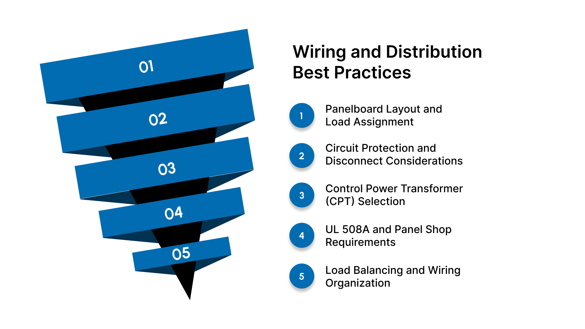
Panelboard Layout and Load Assignment
Correct placement of phases in panelboards reduces the risk of accidental connection to the high leg.
The high leg must always occupy the center lug (B phase) in panelboards and switchgear.
Only phases A and C should be used for 120-volt single-phase loads such as lighting, receptacles, and control power circuits.
The B phase should be reserved strictly for 240-volt and three-phase loads.
Circuit Protection and Disconnect Considerations
Protective devices must be selected and sized to support voltage imbalance and load type.
Breakers and disconnects must be properly rated for 240-volt three-phase service and coordinated with equipment requirements.
Labeling on disconnects and motor control equipment must clearly indicate phase assignment and presence of a high leg.
Control Power Transformer (CPT) Selection
Control systems and panels require special attention when generating low-voltage control power.
CPT primary taps should be connected across A-C where 240 volts is stable and balanced.
Avoid using the high leg for any portion of control power due to the 208-volt to neutral imbalance.
UL 508A and Panel Shop Requirements
Panel builders must account for high-leg conditions in standardization and documentation.
UL 508A requires clear labeling of the high-leg and correct documentation of phase arrangement.
Panel schematics should identify the high leg and include warnings at terminal points.
Load Balancing and Wiring Organization
Good phase balance improves longevity and performance.
Three-phase loads should be distributed evenly across A-B-C to avoid overheating and excessive neutral current.
Clearly marked wiring routes and panel schedules help reduce maintenance errors.
Even with good wiring practices in place, it’s important to recognize the limitations and risks that come with operating a High-Leg Delta service.
System Limitations & Risk Factors
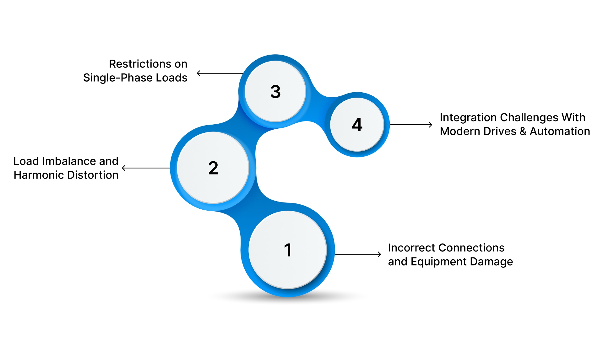
High-Leg Delta systems can operate reliably when properly managed, but misunderstanding their constraints can lead to equipment failure, safety hazards, and costly downtime.
Incorrect Connections and Equipment Damage
Improper wiring is the most common and severe risk associated with High-Leg Delta.
Accidentally connecting a 120-volt load to the high leg exposes equipment to approximately 208 volts, often causing immediate failure of electronics, control circuits, lighting, and receptacles.
Incorrect phase assignment in panelboards or MCCs can result in blown fuses, tripped breakers, or damaged transformers.
Load Imbalance and Harmonic Distortion
High-Leg Delta inherently produces uneven phase loading, which can degrade power quality over time.
Mixed single-phase and three-phase loads can create imbalance, increasing heating in transformers, conductors, and motor windings.
Harmonics are often more pronounced in facilities with high VFD usage when power is unbalanced or poorly filtered, contributing to nuisance trips and reduced equipment lifespan.
Restrictions on Single-Phase Loads
Only specific phases are safe for standard low-voltage equipment.
Single-phase 120-volt loads must be connected only between A-N or C-N.
The high leg (B-N) can never be used for receptacles, lighting, building controls, or PLC power supplies due to its elevated 208-volt to neutral level.
Misapplication often occurs during renovations or panel additions if labeling is unclear.
Integration Challenges With Modern Drives and Automation
Legacy distribution does not always pair smoothly with newer electrical technology.
Variable frequency drives, soft starters, UPS systems, and automation hardware may require stable, balanced voltages or wye-based input supplies.
Using the high leg as part of the drive input or control power can cause instability, excessive heat, or premature failure.
Backup power and generator systems may require neutral bonding and distribution redesign to align with high-leg characteristics.
These limitations often become more noticeable during equipment upgrades or retrofit projects, which is why planning ahead matters.
Upgrading or Supporting Legacy High-Leg Delta Plants
Modernizing a High-Leg Delta facility requires careful planning to avoid costly downtime, ensure compatibility with new equipment, and maintain code compliance.
When to Consider System Conversion
Many facilities evaluate upgrades when equipment demands exceed the limitations of the existing service.
Conversion is recommended when adding large automation systems, modern VFD networks, high-efficiency motors, or sensitive electronic loads.
Full replacement with 208Y/120 or 480Y/277 wye service improves power balance, simplifies load distribution, and reduces long-term maintenance issues.
A full conversion may be necessary when power quality issues or high harmonic levels are affecting reliability or production uptime.
Drive-Based and Phase-Conversion Alternatives
Not every facility can justify a full utility service upgrade immediately.
Rotary phase converters and solid-state phase converters can support three-phase equipment in smaller facilities when loads are low or intermittent.
VFDs can be used as a power conversion solution for individual motors, especially in retrofit applications where full system redesign is impractical.
Drive-based power networks allow equipment upgrades without immediate transformer or switchgear replacement.
Planning for Modernization With Minimal Downtime
Effective upgrade strategies protect production schedules and budget constraints.
A phased migration approach allows facilities to transition equipment gradually rather than shutting down operations.
Panel scheduling, documentation updates, and load mapping help standardize equipment replacements and wiring discipline.
Temporary bypass panels, portable transformer solutions, and staged MCC replacements can maintain uptime during construction.
Upgrades can help, but avoiding common mistakes in everyday work is just as important to keeping systems reliable.
Common Field Mistakes to Avoid
Avoiding these frequent errors can prevent equipment failures, code violations, and unnecessary troubleshooting time.
Treating all three phases as equal and assuming each can support 120-volt loads.
Connecting control circuits, receptacles, or lighting to the high leg by mistake.
Failing to mark the high leg clearly with orange labeling at all termination points.
Placing the high leg in the wrong bus position, rather than the required B-phase location.
Misinterpreting voltage readings due to unfamiliarity with delta vector relationships.
Using protective devices or contactors not rated for the system’s voltage imbalance.
Ignoring power quality issues when installing VFDs, soft starters, or automation equipment.
Neglecting to update panel schedules and wiring diagrams during modifications or expansions.
Assuming modern UPS, generator, or backup systems will integrate seamlessly without engineering review.
Forgetting to evaluate load balancing across phases leads to overheating and transformer stress.
Seeing how these issues play out in real facilities makes the risks and the solutions much easier to understand.
Real-World Application Examples
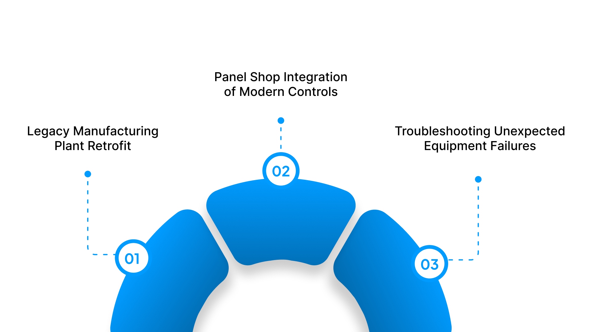
Real installations illustrate why understanding High-Leg Delta wiring is essential for safety, reliability, and successful system upgrades.
Legacy Manufacturing Plant Retrofit
A legacy metal fabrication facility operating on a 240 V High-Leg Delta service planned to modernize part of its production line by adding new VFD-driven motors and automation controls.
Incorrectly wired control circuits were tied into the high leg, exposing 120 V instrumentation and PLC supplies to 208 V
Repeated component failures and troubleshooting delays occurred before the voltage imbalance was identified
Solution included relocating all 120 V loads to A and C phases, applying correct labeling, and installing harmonic filtration for power stability.
Panel Shop Integration of Modern Controls
A UL 508A panel shop needed to build standardized control panels for an OEM using High-Leg Delta service.
CPTs were initially wired across A-B, leading to overheating and transformer damage risk.
Root cause traced to improper primary voltage tap selection and misunderstanding of phase behavior.
Correcting wiring to A-C resolved the issue and reinforced the importance of accurate documentation and schematics.
Troubleshooting Unexpected Equipment Failures
A machine shop experienced unpredictable shutdowns on a CNC machine tied to an older High-Leg Delta distribution system.
Control cabinet power was mistakenly fed from the high leg during a prior panel expansion.
Sensitive electronics designed for 120 V were exposed to approximately 208 V, triggering nuisance trips and corrupting control logic.
Re-routing control power to A-N and C-N restored stable operation and eliminated production downtime.
How ValuAdd Supports Customers Working With High-Leg Delta
Many facilities operating with High-Leg Delta service rely on expert guidance to upgrade equipment safely, avoid downtime, and integrate modern automation. This is where ValuAdd provides critical support.
ValuAdd provides technical sales support and application expertise to OEMs, panel shops, industrial facilities, and electrical distributors across NC, SC, and VA who work with legacy electrical infrastructure such as High-Leg Delta systems. With a complementary portfolio of industrial electrical manufacturers and hands-on field experience, ValuAdd helps customers make informed design and equipment decisions.
Areas of Support and Technical Value
Proper selection of disconnects, MCCBs, motor starters, soft starters, and contactors suited for 240 V three-phase systems and high-leg applications
Power quality solutions, including line reactors, harmonic filters, and drive output filtering to stabilize VFD-heavy environments
Industrial enclosures, climate control, and thermal management products designed for harsh or heat-sensitive installation locations
Monitoring relays, protection devices, and UPS products to safeguard critical control circuits and automation equipment
Local engineering assistance, on-site support, and training to prevent wiring errors, improve code compliance, and ensure long-term reliability
ValuAdd serves as a technical partner rather than a transactional supplier, helping facilities standardize component platforms, solve field challenges efficiently, and modernize aging power systems without unnecessary risk or downtime.
Conclusion
High-Leg Delta systems remain common in legacy industrial facilities, and while they offer valuable mixed-load capability, they also introduce wiring challenges, voltage imbalance, and equipment risk when not properly understood. Correct identification, load placement, and integration practices are critical to maintaining reliability and preventing costly failures.
For facilities upgrading equipment, adding automation, or troubleshooting power issues, expert support can significantly reduce risk and downtime. ValuAdd works closely with OEMs, panel shops, industrial plants, and distributors across NC, SC, and VA to provide technical guidance, application support, and proven solutions for High-Leg Delta environments.
Have a High-Leg Delta question or project in progress? Contact ValuAdd to speak with a technical specialist and get the right support for your application.
Frequently Asked Questions (FAQ)
1. Why is the high leg approximately 208 V to neutral instead of 120 V?
The elevated voltage occurs because of the geometric vector relationship in the delta transformer arrangement. The center-tap neutral divides one winding evenly, but not the third, which creates the higher line-to-neutral voltage.
2. Why must the high leg be placed on the B phase?
The NEC requires the high leg to occupy the center pole of panelboards to prevent wiring mistakes and ensure consistent identification. Placing it elsewhere can lead to unsafe load connections and code violations.
3. Why does the high leg have to be marked orange?
NEC Articles 110.15 and 230.56 mandate orange identification at all termination points to prevent accidental connection of 120-volt loads. Clear marking eliminates ambiguity during service, repairs, and expansions.
4. Can I use the high leg for 120-volt loads?
No. The high leg measures around 208 V to neutral and will damage equipment designed for 120 V. Only A-N and C-N should be used for standard single-phase loads.
5. How does High-Leg Delta affect VFDs and automation systems?
Modern drives and controls require balanced voltages and clean power. High-Leg supplies may require special filtering, proper phase selection, or conversion equipment for stable operation.