Could a decades-old communication standard still be the backbone of modern automation, and outperform newer, fancier options?
Ask any engineer working in a factory or power plant, and many will point to RS‑485 as the unsung hero of industrial networking. With the ability to link dozens of control devices across distances up to 1.2 kilometres, RS-485 remains a go-to for reliable, noise-resistant communication.
That’s why this standard powers a wide array of critical systems, from SCADA and PLC/HMI networks to power-monitoring setups and drive communications. Whether you’re managing a sprawling manufacturing line, supervising energy distribution, or coordinating motor drives, RS-485 delivers the dependable connectivity you need, even in electrically noisy, high-interference environments.
In this post, we’ll explore exactly why RS-485 remains so popular, highlighting its technical strengths and real-world applications across industries.
Key Highlights
RS-485 remains the backbone of industrial communication thanks to its long-distance capability (up to 1.2 km), high noise immunity, and ability to network multiple devices on a single bus.
Differential signaling (A/B lines) makes RS-485 far more stable in electrically noisy environments than RS-232 and significantly cheaper and simpler than Ethernet for field-level control.
Supports up to 32+ devices in a multi-drop network, enabling PLCs, HMIs, VFDs, energy meters, relays, and sensors to share one cable with minimal wiring cost.
Reliable performance depends on correct wiring practices and daisy-chain topology, proper 120 Ω termination, biasing, correct polarity, shield grounding, and avoiding star layouts and long stubs.
Widely used across automation, power monitoring, HVAC, water systems, and SCADA, with ValuAdd offering RS-485-enabled PLCs, meters, relays, and diagnostics to build stable, scalable networks.
What Is RS-485?
RS-485 (also known as TIA/EIA-485) is an electrical signaling standard used for serial communication in industrial and commercial systems. Unlike application-layer communication protocols (such as Modbus, Profibus, or BACnet), RS-485 only defines the physical layer, the electrical characteristics that determine how bits of data are transmitted over wires, not how the data itself is structured or interpreted.
In other words, RS-485 is the foundation that enables reliable data transfer, while the protocol riding on top determines what the data means.
RS-485 vs. RS-232 vs. Ethernet
Feature | RS-485 | RS-232 | Ethernet |
|---|---|---|---|
Transmission Type | Differential balanced signaling | Single-ended signaling | Packet-based networking |
Max Cable Length | Up to ~1200 m | ~15 m | 100 m before needing a switch/repeater |
Max Devices | Up to 32 (expandable with repeaters) | Typically point-to-point only | Thousands via network infrastructure |
Noise Immunity | High (ideal for industrial environments) | Low | Medium-High, depending on the medium |
Cost & Complexity | Low | Low | Medium-High |
Topology | Multi-drop bus | Point-to-point | Switched star/tree |
RS-485 is preferred where long distance, electrical noise, and simple, low-cost wiring are priorities. RS-232 is mainly for short point-to-point links, and Ethernet excels in high-speed data networking and scalability.
Multi-Drop Communication Capability
One of the defining advantages of RS-485 is its ability to support a multi-drop network, meaning multiple devices (nodes) can share the same communication bus. A typical RS-485 network can connect:
1 master device (e.g., PLC, SCADA, HMI)
Up to 31 slave devices (expandable with repeaters and modern transceivers supporting more nodes)
This allows a single cable pair to run through a facility, linking many devices for monitoring and control, significantly reducing installation time and wiring costs compared to point-to-point systems.
How RS-485 Communication Works
RS-485 enables reliable serial communication by using differential signaling, designed to resist electrical noise and support long cable runs common in industrial environments.
To understand why RS-485 is so robust, it helps to explore how its electrical transmission method and wiring structure function.
Differential Signaling Basics
RS-485 uses two signal lines, commonly labeled A (–) and B (+). Instead of referencing signals to ground like RS-232, RS-485 transmits data as the voltage difference between these two wires.
A logical “1” is sent when B > A
A logical “0” is sent when A > B
Because external noise affects both wires equally, the receiving device reads only the difference between A and B, canceling out interference, making RS-485 highly resistant to electrical noise, ground loops, and crosstalk.
Half-Duplex vs. Full-Duplex Operation
RS-485 can be wired in two configurations, depending on communication needs:
Mode | Wiring | Direction of Data | Use Case |
|---|---|---|---|
Half-Duplex (2-wire) | One pair (A/B) shared for TX & RX | One direction at a time | Most common configuration: Modbus RTU |
Full-Duplex (4-wire) | Two pairs (A/B for TX, A’/B’ for RX) | Simultaneous send & receive | HMI-to-PLC links, high-speed applications |
Most industrial RS-485 networks use 2-wire half-duplex, simplifying wiring and allowing dozens of devices on a single shared bus.
Typical RS-485 Network Topologies
The most recommended structure is the daisy-chain (bus) topology, where devices are connected in series along a single cable run. Supported configurations include:
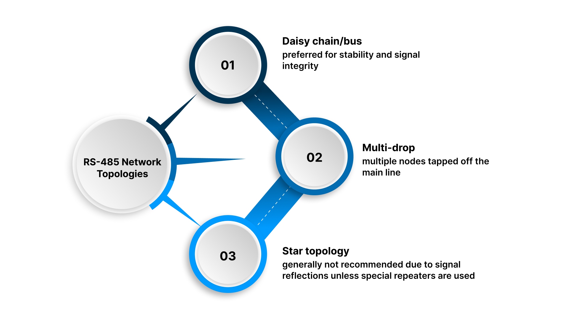
Daisy chain/bus — preferred for stability and signal integrity
Multi-drop — multiple nodes tapped off the main line
Star topology — generally not recommended due to signal reflections unless special hubs/repeaters are used
Proper termination resistors (typically 120 Ω at both ends of the bus) and biasing resistors are important to maintain signal quality.
Distance and Speed Capabilities
The relationship between cable length and data rate is inverse: longer distances require lower speeds. Typical RS-485 performance:
Parameter | Typical Value |
|---|---|
Maximum length | Up to 1200 m (4000 ft) |
Maximum speed | Up to 10 Mbps (at short distances) |
Devices per bus | 32 nodes standard (expandable with repeaters / modern transceivers) |
A common benchmark is:
100 kbps at 1200 m or 1 Mbps at 400 m
This combination of noise-immune signaling, flexible duplex options, simple topologies, and long-distance capability makes RS-485 ideal for robust communication between controllers, sensors, actuators, and monitoring devices across large industrial sites.
RS-485 Wiring Fundamentals
Proper wiring is essential to achieving the reliability and noise immunity that RS-485 is known for. The cabling method, conductor pairing, and topology choices directly impact communication stability across industrial environments.
Wire vs. 4-Wire Configurations
RS-485 can be wired in two main configurations, depending on the desired communication mode:
Configuration | Wires Used | Direction | Typical Use |
|---|---|---|---|
2-Wire (Half-Duplex) | One twisted pair (A/B) | Send or receive at a time | Most common in multi-drop networks, Modbus RTU systems |
4-Wire (Full-Duplex) | Two twisted pairs (TX A/B and RX A’/B’) | Send and receive simultaneously | Point-to-point or master-to-HMI/PLC, high-speed communication |
In multi-drop networks, 2-wire is preferred because all devices share the same pair, simplifying wiring and reducing cost. 4-wire setups are used when real-time parallel communication or higher throughput is required.
Polarity and Conductor Pairing
Consistent polarity across all devices is critical. RS-485 lines are commonly labeled:
A (–) and B (+) — sometimes reversed depending on manufacturer
May also appear as D– / D+, TX– / TX+ or 485– / 485+
Best practices include:
Match A-to-A and B-to-B across every device
Use twisted pair conductors for each signal line pair to maintain electromagnetic balance
Maintain termination resistors (120 Ω) at the two endpoints of the bus to minimize signal reflections
Incorrect polarity is one of the most common installation errors and leads to communication failure or intermittent data issues.
Recommended Cable Types
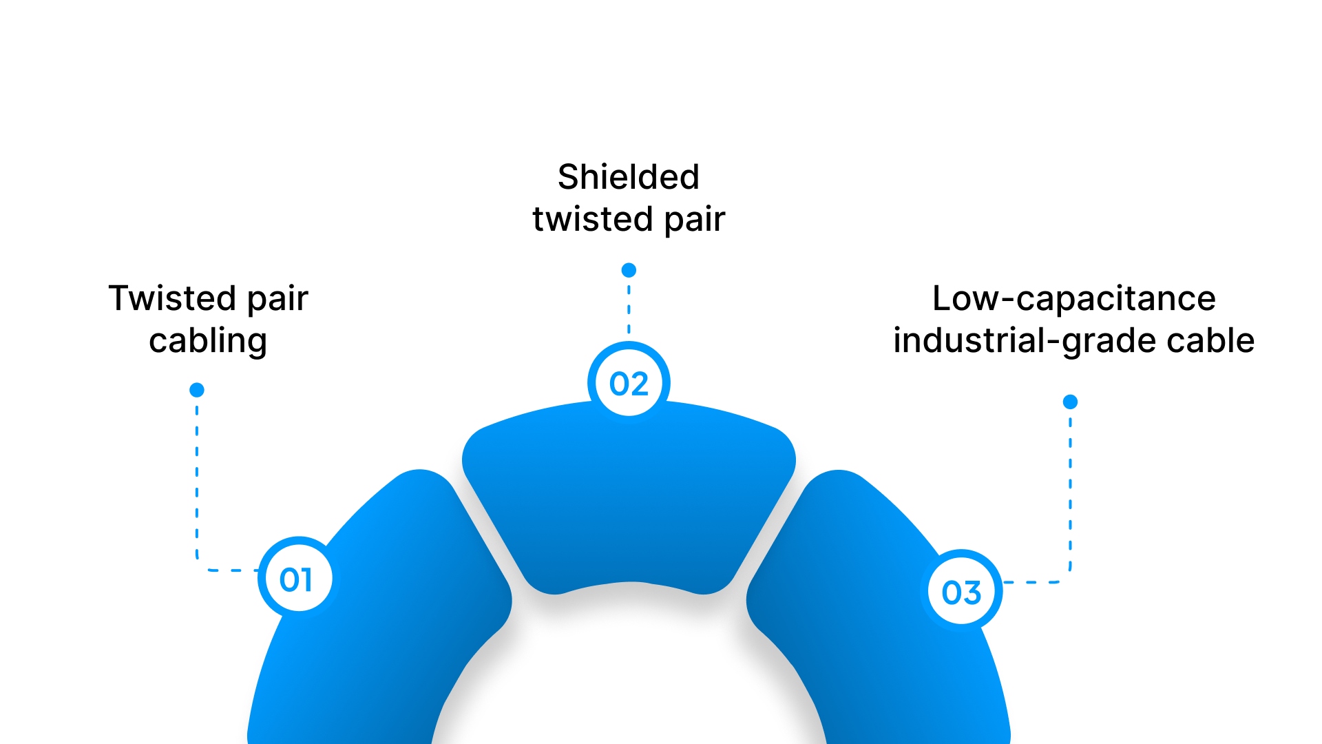
To preserve differential signal quality in noisy industrial environments, use:
Twisted pair cabling (minimizes noise induction)
Shielded twisted pair (STP) for high-interference environments such as VFD rooms or switching stations
Low-capacitance industrial-grade cable for long-distance runs
Common cable examples:
Belden 9841 / 3105A (for single-pair networks)
Belden 9842 / 3106A (for two-pair full-duplex wiring)
The cable shield should typically be grounded at one end only to prevent ground loops.
Cable Length Limitations & Baud Rates
RS-485 performance is closely linked to the balance between cable length and data rate. As distance increases, the maximum achievable baud rate decreases.
Typical guidelines:
Cable Length | Recommended Maximum Baud Rate |
|---|---|
1200 m (4000 ft) | ~100 kbps |
400 m (1300 ft) | ~1 Mbps |
< 50 m (164 ft) | Up to 10 Mbps |
Other factors that affect real-world performance include cable quality, termination, number of nodes, and environment.
Termination & Biasing
Proper termination and biasing are essential design practices that ensure data integrity and reduce interference on RS-485 networks. Without them, even correctly wired systems can experience unstable communication, especially in long-distance or multi-drop installations.
Termination Resistors
RS-485 uses a differential bus that must be electrically stabilized at both physical ends of the main transmission line. To accomplish this, 120-ohm termination resistors are installed across the A and B lines at the two furthest endpoints of the bus.
Why is termination needed?
Prevents reflections caused by signal energy bouncing back along the cable
Maintains clean signal edges for the receiver
Improves reliability at higher baud rates and longer cable runs
Where to install:
One termination resistor at each end of the daisy-chain
Not on intermediate devices
Adding too many termination points increases loading on the bus, degrading the signal. Only two resistors should be used unless repeaters create additional segments.
Bias Resistors
Biasing (also called fail-safe biasing) stabilizes the RS-485 network by forcing the bus to a known idle state when no device is transmitting. This prevents the receiver from reading noise as bits.
Typical biasing values:
Pull-up resistor from B (+) to +V
Pull-down resistor from A (–) to Ground
Combined bias resistance is often in the range of 450–680 Ω, depending on network size
Purpose of bias resistors:
Ensures a defined marking state (logic 1) when the bus is idle
Prevents random transitions caused by electromagnetic interference
Supports a stable line condition before transmission begins
Many modern RS-485 transceiver modules include internal biasing, but only one active bias point should exist per network segment.
Best Practices for Reliable RS-485 Networks
Designing RS-485 networks with proper wiring and installation practices is critical to achieving stable and predictable communication. Poor network design often leads to intermittent failures that are difficult to diagnose.
The following best practices help ensure long-term reliability and performance.
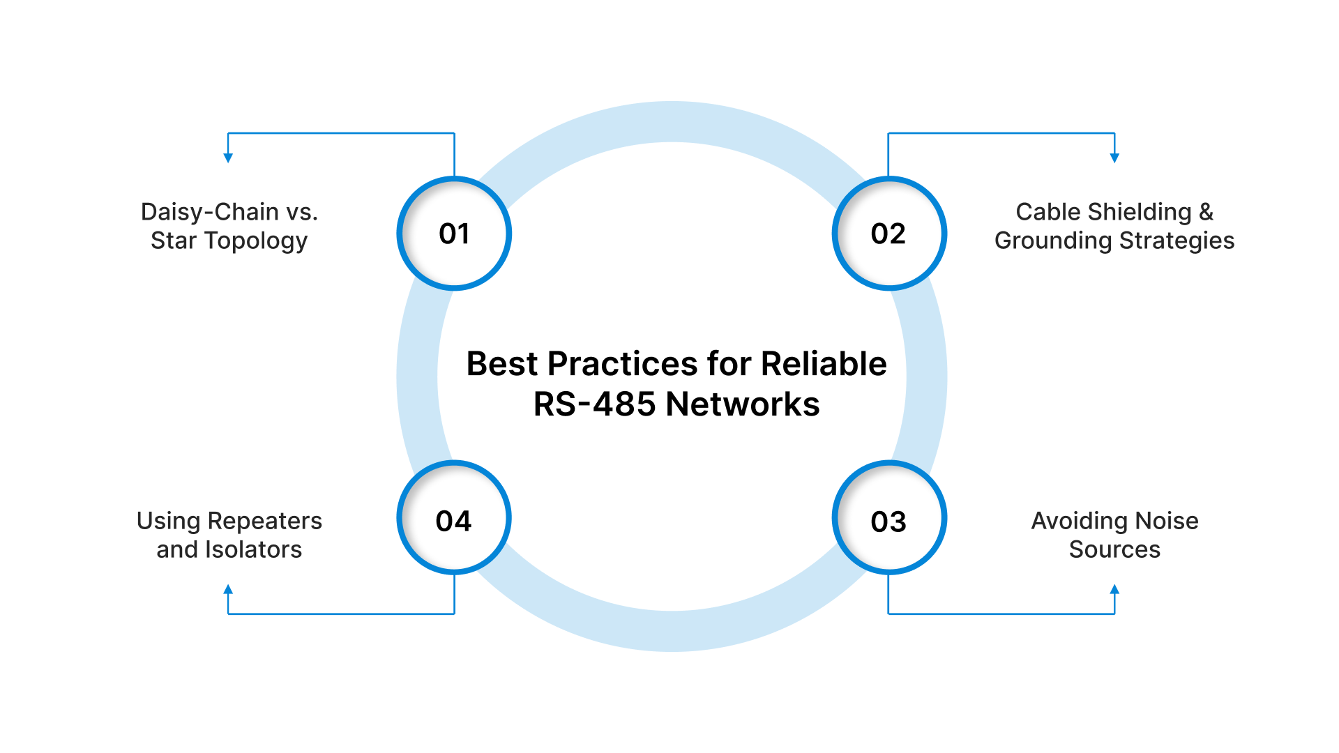
Daisy-Chain vs. Star Topology
The recommended RS-485 network layout is a daisy-chain (bus topology), where each device connects in sequence along a single main cable run.
Why Daisy-Chain Works Best
Maintains a consistent characteristic impedance along the line
Minimizes signal reflections and waveform distortion
Simplifies termination (only at the two bus ends)
Why Star Topology Should Be Avoided
Creates multiple branches (“stubs”) that reflect signals back into the main line
Increases communication errors, especially at high baud rates
Requires special hubs or repeaters to function reliably
Rule of thumb: Keep any unavoidable “stub” length under 30 cm (12 in), and avoid splitting the bus unnecessarily.
Cable Shielding & Grounding Strategies
Shielding protects differential signals from electromagnetic interference (EMI), especially in industrial sites with motors, welding machinery, and switching equipment.
Recommended grounding practices:
Ground the cable shield at one end only to prevent ground loops
Connect the shield to the control cabinet’s protective earth (PE)
Use shielded twisted-pair (STP) cable for high-noise areas
If multiple building grounds are involved, consider isolated repeaters to prevent circulating current and voltage differences.
Avoiding Noise Sources
Electrically noisy environments can degrade RS-485 signals, even with differential signaling. To reduce interference:
Avoid routing communication cabling near VFD output cables, high-current feeders, relay coils, contactors, welders, and lightning/arcing equipment
Keep RS-485 cable separated from power cables by at least 30 cm (1 ft), more for high-power VFD systems
If crossing power lines, do so at 90 degrees rather than parallel
Using Repeaters and Isolators
For long cable runs or harsh electrical environments, adding hardware conditioning can enhance network reliability.
Repeaters
Extend the total network length beyond 1200 m
Increase the number of addressable devices beyond 32 nodes
Regenerate signals and improve timing
Isolators
Break ground-loop paths between segments
Protect equipment from surges and voltage differences
Improve EMC performance and reduce faults from floating grounds
These devices are especially useful in power plants, mining, steel mills, and distributed building automation systems.
Real-World Industrial Applications of RS-485
RS-485 remains a dominant communication standard across industrial and commercial environments due to its long-distance capability, noise immunity, and ability to network multiple devices at low cost.
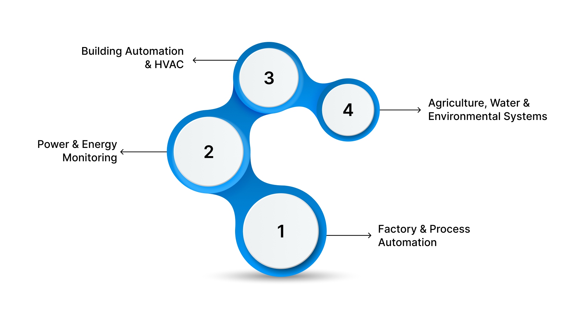
Factory & Process Automation
RS-485 links sensors, actuators, controllers, and field devices across production lines and processing facilities.
Typical use cases
PLC-to-drive communication (VFDs, servo drives, soft starters)
HMI operator panels connected to controllers
Remote I/O modules distributed along conveyors or equipment
Industrial robots and automated assembly equipment
Its multi-drop bus structure makes it ideal for systems where dozens of field devices must be monitored in real time over long distances.
Power & Energy Monitoring
RS-485 is standard in power distribution networks due to its reliability in electrically harsh environments.
Energy meters & power quality analyzers
Solar inverters and battery storage systems
Substation automation
Generator control systems
EMS/BMS energy management platforms
Modbus RTU over RS-485 is the industry norm for power factor, load, harmonics, and consumption monitoring across campuses and industrial facilities.
Building Automation & HVAC
In modern smart buildings, RS-485 connects distributed devices that manage comfort, efficiency, and safety.
Examples
BACnet MS/TP for HVAC, chillers, VAVs, and AHUs
Lighting control systems
Access control & security panels
Fire alarm control systems
Environmental sensors (CO₂, temperature, humidity)
The long cabling distance and noise rejection allow controllers on different floors or wings to communicate without Ethernet infrastructure complexity.
Agriculture, Water & Environmental Systems
SCADA RTU communication for water treatment and pumping stations
Irrigation and greenhouse automation
Weather & soil condition monitoring networks
Often, these systems span kilometers of outdoor cabling exposed to electrical storms and interference.
Common Issues and Troubleshooting Tips
Even well-designed RS-485 networks can encounter issues caused by wiring mistakes, electrical interference, or configuration errors. Because problems often appear intermittently, especially under load or environmental changes, a structured troubleshooting approach is essential.
Intermittent Data Loss or Device Offline Symptoms
Many RS-485 failures present as random communication drops, timeouts, or devices becoming offline despite correct settings. Typical symptoms include:
Data read failures or corrupted Modbus packets
Devices responding inconsistently or only at low baud rates
Communication failures after adding new nodes or extending wiring
Errors that occur only when nearby motors or VFDs start
Devices are working temporarily after power cycling
In most cases, these issues are traced to physical layer problems such as improper termination, noise coupling, incorrect polarity, or grounding faults.
Diagnostic Tools for RS-485 Troubleshooting
Using the right tools helps isolate the problem quickly:
Tool | What it Helps Diagnose |
|---|---|
Digital Multimeter (DMM) | Check bias voltage (bus idle should read > 200 mV between A/B) |
Oscilloscope | Inspect the differential waveform for reflections, ringing, or noise |
Protocol analyzer / USB-RS485 adapter | Decode messages & confirm addressing/CRC issues |
Line tester / LED monitors | Verify activity and node response |
Cable tester / TDR | Detect shorts, opens, or incorrect pinout |
A clean RS-485 differential waveform should look stable with well-defined high/low transitions and minimal overshoot.
6 Typical Installation Errors & Field Lessons
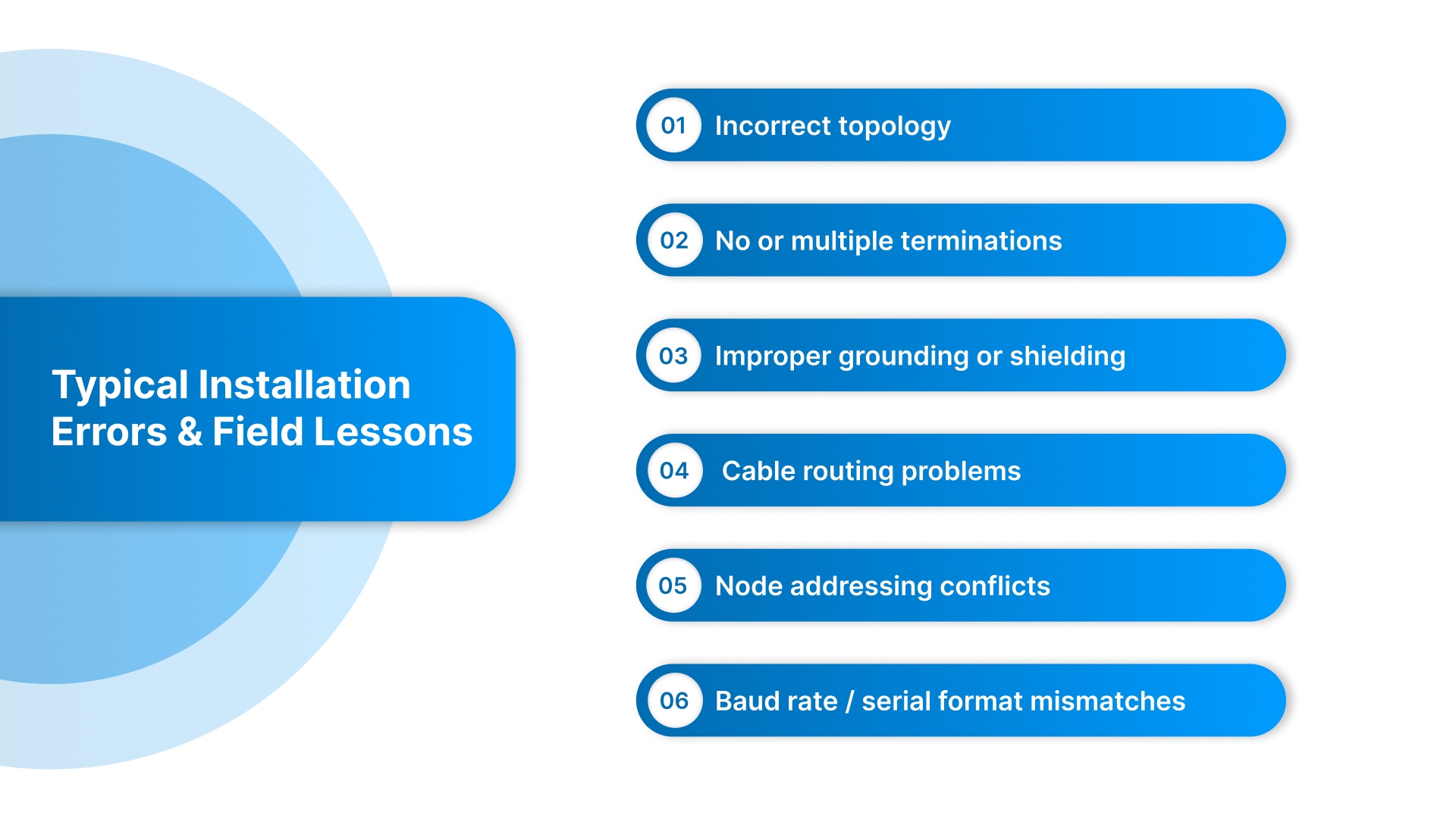
Common mistakes seen in real installations include:
1. Incorrect topology
Star topology instead of daisy chain → reflections & corrupted frames
2. No or multiple terminations
Missing termination: works only at slow speeds or short distances
Extra terminations: signal too weak to be decoded reliably
3. Improper grounding or shielding
Shield grounded at both ends → ground loop noise
Shield not grounded at all → susceptible to EMI
4. Cable routing problems
RS-485 cable tied into VFD output conduit or power trunking
Long stubs from T-junctions
5. Node addressing conflicts
Two devices with the same Modbus ID behave as if one is offline
6. Baud rate / serial format mismatches
Mismatched baud, parity, stop bits, or timeout settings prevent communication.
How ValuAdd Strengthens RS-485-Based Automation & Monitoring Systems
ValuAdd supports industrial OEMs, panel shops, distributors, and facility engineers across South Carolina, North Carolina, and Virginia with hardware solutions that fully leverage RS-485 and Modbus RTU for reliable communication, long-distance networking, and seamless SCADA connectivity.
CIMON – PLCs, HMIs, and Industrial PCs
Controls hardware with built-in RS-485 and native Modbus RTU
Ideal for linking VFDs, sensors, power meters, and remote I/O across production lines
Socomec – Power & Energy Monitoring Systems
RS-485/Modbus-enabled energy meters and power analyzers
Real-time visibility into loads, power quality, consumption, and alarms for SCADA/EMS/BMS.
TCI – Power Quality Hardware
Harmonic mitigation and diagnostic solutions with RS-485 reporting.
Enables monitoring of distortion and drive-related power issues remotely.
Macromatic / Finder – Control & Monitoring Relays
RS-485 communication for status, fault reporting, and predictive-maintenance insight.
Connects equipment health data directly to PLCs or SCADA platforms.
NOARK Electric – Circuit Protection & Switching Devices
Protection devices with RS-485 event and trip data.
Supports remote monitoring of electrical protection and load performance.
RS-485 integration through ValuAdd centralizes data from distributed field devices, lowers wiring costs, and simplifies SCADA connectivity and remote diagnostics. It also scales effortlessly as systems grow and supports long-distance communication across industrial sites, campuses, and municipalities.
Conclusion
RS-485 continues to stand as a proven, dependable communication standard in modern industrial automation. Its long-distance capability, noise immunity, and multi-drop networking make it ideal for SCADA, PLC/HMI systems, energy monitoring, and distributed control across industrial plants, OEM machinery, building automation, and municipal infrastructure.
When combined with best-practice installation and properly engineered device selection, RS-485 delivers high reliability with low cost and simple scalability.
As facilities push toward smarter operations, real-time visibility, and predictive maintenance, RS-485 remains a critical link between field equipment and supervisory systems, enabling modernization without full system replacement or complex networking upgrades.
ValuAdd provides a focused portfolio of RS-485-enabled automation, energy monitoring, and protection solutions, helping customers design robust networks and integrate field-level data into SCADA and control architectures efficiently. Consult a ValuAdd expert for quick, accurate component guidance.
Frequently Asked Questions (FAQ)
1. How many devices can be connected to an RS-485 network?
A standard RS-485 bus supports 32 nodes, but this can be expanded with repeaters or modern transceivers. All devices share the same twisted-pair cable in a multi-drop configuration.
2. Why is RS-485 preferred for Modbus RTU?
Modbus RTU’s polling structure aligns perfectly with RS-485’s half-duplex multi-drop design. This allows many field devices to communicate reliably over long distances at low wiring cost.
3. What causes most RS-485 communication issues?
Common causes include incorrect termination, improper grounding, star topologies instead of daisy-chains, long stubs, polarity reversal, and electrical noise from power equipment like VFDs.
4. What is the proper wiring topology for RS-485?
A linear daisy-chain is the recommended configuration to ensure signal integrity. Star topologies cause reflections and should be avoided unless hubs or repeaters are used.
5. What are termination and biasing resistors used for?
Termination prevents signal reflections at cable ends, while biasing ensures a stable idle state and prevents noise from being interpreted as data. Both are essential for reliable communication.
.