
Introduction
Integrating power meters and HMIs into multi-device networks creates real headaches: analog signals introduce noise and drift, wiring complexity drives up labor costs, and poor data visibility leaves energy waste undetected.
A facility running 4-20 mA loops for energy monitoring needs separate wire pairs for voltage, current, power factor, and harmonic distortion—a tangled infrastructure that consumes panel space and complicates every inspection.
Modbus solves this with a single two-wire or Ethernet connection that carries dozens of parameters—voltage per phase, active and reactive power, total harmonic distortion (THD), and cumulative kWh—from each addressed device. Originally published by Modicon in 1979, it's now an open standard deployed in SCADA systems, PLCs, variable frequency drives, and power meters across virtually every industrial sector.
What follows covers the practical decisions engineers encounter: how each Modbus variant works, how power meters map electrical parameters to registers, and how HMIs connect directly to meters without a PLC in the loop.
TLDR:
- Modbus transmits multi-variable data from one two-wire or Ethernet connection, replacing multiple analog loops
- RTU uses binary encoding over RS-485; TCP wraps messages in Ethernet packets on port 502
- Power meters expose voltage, current, kW, kVAR, power factor, frequency, THD, and kWh via holding/input registers
- HMIs poll meters directly—no PLC required—on IP65/IP66/IP68-rated displays
- IEEE 519 compliance in VFD-equipped facilities depends on THD tracking via Modbus registers
How Modbus Works: Architecture and Core Communication Model
Modbus is an application-layer serial communication protocol developed by Modicon in 1979, now maintained as an open standard by the Modbus Organization. It defines client/server communication between devices on the same network, enabling PLCs, SCADA systems, and HMIs to query power meters, variable frequency drives, and sensors over a shared communication standard.
Master/Slave Architecture
Modbus operates on a polling-based master/slave (client/server) model: one master device initiates requests, and one or more slave devices respond only when addressed. The master sends a query containing:
- Slave address (1–247, with 0 reserved for broadcast)
- Function code (defines the operation, e.g., read or write)
- Data (register addresses and quantity)
- Error check (CRC for RTU, LRC for ASCII)
Only the addressed slave replies; other devices on the network ignore the message. This ensures collision-free communication on shared media like RS-485 buses.
Four Primary Data Types
Modbus organizes data into four tables, each serving distinct I/O needs:
| Data Type | Access | Size | Typical Use |
|---|---|---|---|
| Coils | Read/Write | 1-bit | Relay outputs, digital control signals |
| Discrete Inputs | Read-Only | 1-bit | Binary sensor states, alarm flags |
| Holding Registers | Read/Write | 16-bit | Setpoints, configuration parameters |
| Input Registers | Read-Only | 16-bit | Measured process variables (V, A, kW, THD) |
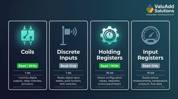
Power meters typically expose electrical parameters—voltage, current, power, frequency, and THD—through holding registers (for configurable values like demand intervals) and input registers (for live measurements).
Function Codes for Power Metering
The most relevant Modbus function codes for power meters and HMIs are:
- FC03 (Read Holding Registers) — retrieves configurable or stored values, such as accumulated energy (kWh) or demand windows
- FC04 (Read Input Registers) — reads real-time measurements like voltage, current, active power (kW), reactive power (kVAR), and THD
- FC06 (Write Single Register) — writes configuration parameters such as CT ratios, PT ratios, or alarm thresholds
Polling Interval and Response Latency
Because Modbus is polling-based, the master queries each slave in sequence. Response latency depends on three factors:
- Number of slaves on the bus — more devices extend the total cycle time
- Baud rate — higher speeds reduce frame transmission time
- Polling interval — the delay between successive queries to the same device
Most power meters refresh internal data every second. Polling more frequently than that returns duplicate readings and wastes bus bandwidth — so matching your poll rate to the meter's update rate matters.
Schneider Electric recommends a minimum 5-second polling interval for meters like the PM5000, balancing data freshness against network load. As a practical rule, most installations cap at 30–32 meters per gateway before polling cycles must lengthen to prevent communication timeouts.
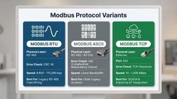
Modbus Variants: RTU, ASCII, and TCP/IP Compared
Modbus implementations vary by encoding, physical medium, and error-checking method. The three dominant variants (RTU, ASCII, and TCP/IP) each suit different infrastructure and performance requirements — knowing which fits your environment saves significant integration effort.
Modbus RTU
Modbus RTU (Remote Terminal Unit) uses binary encoding of messages, producing compact frames that maximize throughput on serial networks. Each 8-bit byte contains two 4-bit hexadecimal characters. Error detection relies on a 16-bit CRC (Cyclical Redundancy Check) appended to each frame.
Key characteristics:
- Physical layer: RS-485 (or RS-232 for point-to-point links)
- Frame overhead: Minimal; binary encoding uses fewer bytes than ASCII
- Error checking: CRC-16 (2 bytes)
- Typical baud rates: 9,600 or 19,200 bps (up to 115,200 bps)
- Silent interval: 3.5 character times between frames
Modbus RTU is the **dominant variant in industrial power monitoring** because it is faster and more bandwidth-efficient than ASCII, and RS-485's differential signaling provides superior noise immunity over long cable runs.
Modbus ASCII
Modbus ASCII encodes each 8-bit byte as two hexadecimal ASCII characters (e.g., 0x3A becomes the ASCII characters 3 and A). This doubles the message size compared to RTU. Error detection uses an LRC (Longitudinal Redundancy Check).
Key characteristics:
- Physical layer: RS-485 or RS-232
- Frame overhead: High; every byte becomes two ASCII characters
- Error checking: LRC (1 byte)
- Use cases: Older systems, longer cable runs where character framing aids synchronization
- Bandwidth: Roughly half that of RTU for the same data payload
ASCII is less common in modern installations but remains useful for legacy equipment or systems requiring human-readable diagnostics on a terminal.
Modbus TCP/IP
Modbus TCP/IP encapsulates the standard Modbus Protocol Data Unit (PDU) inside a TCP packet. Instead of a slave address and CRC, it uses a 7-byte MBAP header (Modbus Application Protocol header) that includes transaction ID, protocol ID, length, and unit identifier. TCP's own checksums handle error detection, so the Modbus CRC is omitted.
Key characteristics:
- Physical layer: Ethernet (10/100/1000 Mbps)
- Reserved port: TCP port 502
- Error checking: TCP checksums (no Modbus CRC)
- Scalability: Supports hundreds of devices on switched Ethernet networks
- Integration: Connects directly to plant-level IT networks, SCADA servers, and cloud platforms
Comparison Table
| Feature | Modbus RTU | Modbus ASCII | Modbus TCP |
|---|---|---|---|
| Encoding | Binary | Hexadecimal ASCII | Binary (TCP-encapsulated) |
| Physical Medium | RS-485, RS-232 | RS-485, RS-232 | Ethernet |
| Error Check | CRC-16 | LRC | TCP checksum |
| Typical Speed | 9,600–19,200 bps | 1,200–19,200 bps | 10–1,000 Mbps |
| Max Devices/Segment | 32 (up to 256 with repeaters) | 32 (up to 256 with repeaters) | Limited by network architecture |
| Ideal Use Case | Legacy RS-485 field wiring | Older systems, diagnostic terminals | Modern Ethernet infrastructure, SCADA integration |
Choosing the Right Variant
The choice of Modbus variant is determined by existing infrastructure:
- RS-485 field wiring already in place? RTU delivers the speed and bandwidth efficiency you need
- Ethernet-connected plant floor? TCP/IP scales easily and connects directly to SCADA and IT systems
- Maintaining older equipment or terminal diagnostics? ASCII's human-readable framing still earns its place
Most industrial-grade power meters and HMIs support at least Modbus RTU and TCP, enabling flexible deployment across mixed-vintage networks.
Modbus Communication for Power Meters
Modbus power meters continuously measure and expose a rich set of electrical parameters via registers, transforming a single two-wire or Ethernet connection into a comprehensive energy monitoring link.
Electrical Parameters Accessible via Modbus
A typical Modbus power meter monitors and transmits:
- Voltage (V) — line-to-neutral or line-to-line, per phase
- Current (A) — per phase
- Active Power (kW) — real power consumed or generated
- Reactive Power (kVAR) — power oscillating between source and load
- Apparent Power (kVA) — vector sum of active and reactive power
- Power Factor — ratio of active to apparent power
- Frequency (Hz) — line frequency
- Total Harmonic Distortion (THD) — percentage distortion of voltage or current waveforms
- Cumulative Energy (kWh) — integrated energy consumption over time
- Demand values — peak kW over defined intervals
IEEE 519 compliance requires monitoring THD to keep voltage and current distortion within acceptable limits at the point of common coupling (PCC). For low-voltage systems (≤ 1.0 kV), IEEE 519-2014 sets a THD voltage limit of 8.0%.
Facilities running variable frequency drives (VFDs) and other non-linear loads must track these parameters to protect equipment and comply with utility interconnection agreements.
Register Mapping
Each electrical parameter is assigned a specific holding register or input register address. The master (PLC, SCADA gateway, or HMI) reads these addresses at a defined poll rate to retrieve live values.
Example register map snippet:
- Register 3000: Phase A voltage (V)
- Register 3002: Phase A current (A)
- Register 3004: Active power (kW)
- Register 3020: Total harmonic distortion, voltage (%)
- Register 4000: Cumulative energy (kWh)
The meter's register map (documented in its datasheet) is essential for correct configuration. Without it, engineers cannot build accurate tag lists or configure SCADA polling queries.
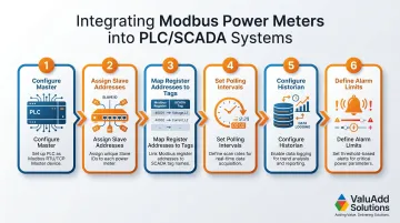
Integration with SCADA and PLC Systems
Modbus power meters integrate into control systems by designating the PLC or SCADA gateway as the Modbus master. The master continuously polls meters on the RS-485 bus or TCP network, logging data to a historian and triggering alarms when thresholds are exceeded.
Typical integration workflow:
- Configure the PLC or SCADA gateway as Modbus master
- Assign unique slave addresses to each power meter (1–247)
- Map register addresses to PLC tags or SCADA points
- Set polling intervals (typically 5–10 seconds per device)
- Configure historian for time-stamped data storage
- Define alarm limits for voltage sag, overcurrent, power factor, and THD
Rockwell Automation's RSEnergyMetrix, for example, uses an integral Modbus RTU master driver to poll PowerMonitor devices. Siemens LOGO! and S7 PLCs utilize Modbus TCP to query SENTRON PAC3200 meters.
Data Logging and Trending
Collected register data can be time-stamped and stored for:
- Energy auditing — track consumption by time of day, shift, or production line
- Load profiling — identify peak demand periods to optimize utility rate schedules
- Demand charge management — reduce peaks to lower monthly demand charges
- Compliance reporting — demonstrate IEEE 519 adherence to utilities or regulators
This data is especially valuable for manufacturing and water treatment facilities, where energy costs represent a significant share of operating budgets.
ValuAdd's IEEE 519-Compliant Power Monitoring Solutions
For facilities that must track harmonic distortion alongside standard energy parameters, ValuAdd offers two purpose-built solutions.
The DIRIS B power meter supports Modbus RTU communication via RS-485, delivers Class 0.2 accuracy per ANSI C12.20, and monitors up to four independent circuits from a single DIN-rail module. The DIRIS Digiware C-31 acts as an RS-485 system interface for centralized data management, transferring multi-point metering data directly to external software or PLC systems.
Both products are well-suited to environments with VFDs and non-linear loads, where THD monitoring is critical to preventing equipment damage and maintaining IEEE 519 compliance.
Industrial HMIs and Modbus Integration
Industrial HMIs simplify power monitoring by connecting directly to Modbus networks as master devices, eliminating the need for a separate PLC or SCADA server in smaller installations.
HMI as Modbus Master
An HMI equipped with a native Modbus driver can poll power meters and other field devices (drives, soft starters, sensors) over RS-485 or Ethernet, then display live values, trends, and alarm states on-screen. The HMI queries each slave device in sequence, retrieves register data, and updates graphical elements in real time.
Benefits:
- Reduces system cost by eliminating standalone PLCs for monitoring-only applications
- Cuts architecture down to panel level for machine-mounted or local installations
- Provides local visualization without requiring network connectivity to a central SCADA server
Configuration Process
Configuring an HMI for Modbus communication involves:
- Set the communication driver to Modbus RTU (serial) or Modbus TCP (Ethernet) in the HMI software
- Enter slave device addresses: Assign each meter or sensor a unique address (1–247)
- Link Modbus register addresses to on-screen display tags in the tag database
- Set polling intervals to a query frequency that suits your process — typically 5–10 seconds per device
- Design HMI screens: Create numeric displays, trend charts, and alarm indicators
Most industrial HMI platforms—including Siemens WinCC Unified, Rockwell PanelView, and Schneider Magelis—include native Modbus drivers that simplify setup and eliminate the need for third-party gateways.
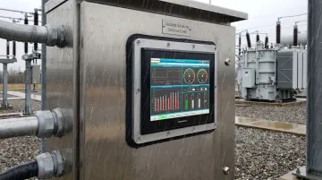
Display Hardware for Demanding Environments
HMIs deployed in industrial power monitoring must meet strict environmental ratings:
- Enclosure ratings: IP65, IP66, or IP68 ensure dust-tight seals and protection against water jets or immersion
- High-brightness screens: 1,000–1,200 nits enable readability in direct sunlight or high-ambient-light installations
- Wide operating temperature ranges: -20°C to +70°C (-4°F to +158°F) supports cold storage and hot process areas
ValuAdd's Cimon eXT2 series industrial displays feature IP68 front protection, 1,200 cd/m² brightness, and aluminum enclosures rated for NEMA Type 4X and 12 compliance. These specs suit panel builders working in washdown areas, outdoor substations, and dusty manufacturing floors. Standard commercial displays won't survive those conditions.
RS-485 Physical Layer: Wiring, Topology, and Device Limits
Get the physical layer wrong and no amount of software configuration will save your Modbus RTU network. RS-485 wiring rules are strict — but straightforward once you know the critical points.
RS-485 Fundamentals
RS-485 is a differential signaling standard that transmits data over a twisted-pair cable. Differential signaling rejects common-mode noise, making RS-485 inherently robust in electrically noisy industrial environments. Key specifications include:
- Cable length: Up to 4,000 feet (1,200 meters) at baud rates below 90 kbps
- Device count: 32 unit loads per segment without repeaters
- Topology: Linear bus (daisy-chain) with termination resistors at both ends
Recommended Network Topology
The RS-485 standard specifies a daisy-chain (linear bus) topology — devices connected in series along a single trunk cable. Star topologies create signal reflections from impedance mismatches at branch points; avoid them for most installations.
Some manufacturers support a star-with-hub configuration for specific meter deployments, but this requires specialized hub hardware to maintain signal integrity and is the exception, not the rule.
Best practice:
- Run a single trunk cable from the master to the farthest slave
- Tap each meter or device with short stub cables (under 12 inches)
- Install 120-ohm termination resistors at both ends of the trunk to match the cable's characteristic impedance and prevent reflections
Device Limits and Polling Performance
A standard RS-485 driver supports 32 unit loads. Using fractional unit-load receivers (e.g., 1/4 or 1/8 unit load) extends this to 128 or 256 devices per segment. However, practical polling performance typically limits installations to 30–32 meters per gateway before polling cycle time grows unacceptable.
Each device added to the network extends the total polling cycle. Exceed 32 devices without adjusting poll intervals and communication timeouts follow. System designers must factor both device count and required poll rate into their response time budgets.
For installations exceeding 32 devices, use RS-485 repeaters to segment the network or deploy multiple gateways — each handling a defined subset of meters.
Modbus vs. 4-20 mA Analog Signals: Choosing the Right Approach
Understanding when to specify Modbus versus 4-20 mA analog loops depends on data richness, wiring complexity, and legacy infrastructure.
Key Differences
4-20 mA current loops transmit a single process variable per wire pair. The current signal is proportional to the measured value — for example, 4 mA = 0 kW and 20 mA = 100 kW. A live zero at 4 mA lets the receiving system distinguish a valid zero reading from a fault like a broken wire.
Current signals are highly resistant to electrical noise and can travel long distances without degradation, which is why analog loops remain common in older facilities and intrinsically safe zones.
Modbus is a digital, multi-variable, addressable protocol. A single RS-485 two-wire connection or Ethernet link can transmit dozens of parameters — voltage, current, kW, kVAR, power factor, frequency, THD, kWh — from each addressed device. A single Modbus connection can replace eight or more separate analog loops on a typical power meter installation.
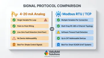
| Feature | 4-20 mA Analog | Modbus (RTU/TCP) |
|---|---|---|
| Data Capacity | Single variable per loop | Multiple variables and diagnostics |
| Wiring | Point-to-point (one pair per variable) | Multi-drop (RTU) or Ethernet (TCP) |
| Fail-Safe | Live zero (4 mA) detects faults | Requires software timeouts/heartbeats |
| Addressability | None (one transmitter per loop) | Up to 247 devices per master |
| Best Use | Simple, critical control signals | Smart systems, SCADA, multi-variable data |
The right choice depends less on which protocol is "better" and more on what your existing infrastructure supports and how many variables you need to move. Here's when each approach makes sense.
When 4-20 mA Is Still Appropriate
- Simple single-variable sensing — transmitting one flow rate or one temperature over a dedicated loop
- Legacy infrastructure — existing wiring and receivers are already in place
- Intrinsically safe zones — where explosion-proof analog isolators are required
- Critical control loops — where fail-safe live-zero detection is mandatory
When Modbus Is the Better Choice
- Multi-parameter power monitoring — voltage, current, power, harmonics, and energy from one connection
- Networked devices — multiple meters on one RS-485 bus or Ethernet switch
- Integration with PLCs and HMIs — digital protocols eliminate analog-to-digital conversion errors
- Data logging and remote configuration — write setpoints, query diagnostics, and trend historical data
For power metering specifically, Modbus is almost always the right call. Reducing eight analog loops to one RS-485 run cuts wiring labor, panel space, and I/O card costs — and gives you far more data to work with.
Frequently Asked Questions
What is the difference between meter bus and Modbus?
M-Bus (Meter-Bus) is a European standard (EN 13757) specifically designed for utility meter reading—heat, water, and gas meters—over two-wire networks. Modbus is a general-purpose industrial communication protocol used in automation, SCADA, and power monitoring. The two are distinct and not interchangeable, though both are deployed in energy metering applications.
Is Modbus 485 or 232?
Modbus is a protocol, not a physical standard. It can run over RS-485, RS-232, or Ethernet (TCP/IP). RS-485 is by far the most common physical layer for industrial Modbus installations because of its noise immunity, multi-drop capability, and cable distance advantages over RS-232.
Is Modbus the same as 4-20mA?
No. 4-20 mA is an analog current loop for transmitting a single variable per wire pair. **Modbus is a digital serial protocol** that transmits multiple data points simultaneously over an addressed network. Modbus power meters replace multiple analog loops with a single RS-485 or Ethernet connection.
What data can a Modbus power meter measure and transmit?
A Modbus power meter exposes all key electrical parameters via register reads from a PLC, SCADA system, or HMI, including:
- Voltage, current, frequency
- Active power (kW), reactive power (kVAR), apparent power (kVA)
- Power factor, total harmonic distortion (THD)
- Cumulative energy (kWh) and demand values
Can an industrial HMI communicate directly with a Modbus power meter without a PLC?
Yes. Most industrial HMIs include a native Modbus RTU or TCP driver and can act as a Modbus master, polling meters directly and displaying live data without an intermediate PLC. This simplifies the setup for smaller installations or machine-level monitoring.
How many Modbus devices can be connected on one RS-485 network?
A standard RS-485 segment supports up to 32 unit loads without repeaters; adding repeaters or low-load transceivers (1/4 or 1/8 unit load) extends this to 128–256 devices. In practice, most installations cap at 30–32 meters per gateway to keep polling intervals at acceptable response times.