
Introduction
Many industrial facilities unknowingly incur substantial power factor penalties, with utilities often charging surcharges that can inflate electricity bills by 10–20% when power factor drops below thresholds like 0.85 or 0.90. Power factor correction (PFC) is the process of adding reactive compensation equipment to an electrical system to bring the ratio of real power to apparent power closer to unity. Done right, it directly addresses utility penalties, cable losses, and degraded equipment performance.
This guide is written for plant engineers, electrical engineers, and system integrators at manufacturing plants, water treatment operations, oil and gas processing facilities, and other environments where inductive motor loads dominate.
Utility bills reference power factor routinely, but operational-level explanations are rare. What follows covers how PFC works in industrial settings, why it matters financially and operationally, how to size and position correction equipment, and critically, when not to use it.
Key Takeaways
- Power factor measures how efficiently a plant converts apparent power (kVA) into real working power (kW); a low power factor means drawing more current than the load actually requires
- Plants with heavy inductive loads (motors, transformers) face utility penalty charges when power factor drops below 0.9–0.95
- PFC adds capacitive reactive power (kVAR) locally to offset inductive demand, reducing line current and freeing up transformer and conductor capacity
- Choosing fixed, automatic, or dynamic correction depends on how much your load varies across production cycles
- Harmonic-heavy environments require detuned or filtered solutions; overcorrection can destabilize generators and UPS systems
What Is Power Factor Correction?
Power factor is the ratio of real power (kW) to apparent power (kVA). A plant drawing 800 kVA to deliver only 640 kW of useful work has a power factor of 0.80, meaning 20% of the current flowing through cables, transformers, and switchgear is non-working reactive current that produces no output but causes losses and triggers utility charges.
Power factor correction addresses this inefficiency by locally supplying the reactive power that inductive loads would otherwise draw from the grid. Adding capacitive reactive power near the loads that need it reduces total current flowing upstream, producing three measurable results:
- Shrinks I²R losses in cables and transformers
- Lowers utility demand charges
- Frees transformer and cable capacity without infrastructure upgrades
PFC vs. Harmonic Filtering
PFC specifically corrects the displacement component of reactive power—the lagging current caused by inductive loads like motors and transformers. This is fundamentally different from harmonic filtering, though both are often needed together when variable-frequency drives (VFDs) or non-linear loads are present. PFC addresses the phase angle between voltage and current; harmonic filters address distorted current waveforms.
Why Industrial Plants Use Power Factor Correction
Utility Penalty Structures
Most power supply agreements penalize industrial customers whose monthly average power factor falls below a threshold, commonly 0.9 or 0.95 depending on the utility and tariff class. Oncor applies a billing demand adjustment where billed kW is increased using the formula: Billed kW = (Actual kW × 0.95) / Actual PF when power factor drops below 0.95.
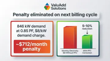
For a plant with 846 kW demand at 0.85 PF facing an $8/kW demand charge, the monthly penalty reaches approximately $712. For facilities with power factors in the 0.55–0.65 range, surcharges can constitute 5–10% of the total electricity bill. Unlike energy efficiency upgrades that reduce consumption gradually, PFC penalty elimination shows up in full on the next billing cycle.
Capacity and Infrastructure Benefits
Correcting power factor reduces apparent power demand (kVA), allowing existing transformers and cables to serve greater active load without capital upgrades. Improving PF from 0.80 to 0.95 increases usable kW capacity by approximately 19% for the same transformer rating.
Example: A 500 kVA transformer loaded at 360 kW with 0.75 PF is effectively at capacity (480 kVA). Correcting to 0.95 PF reduces demand to 379 kVA, freeing up 101 kVA of capacity for expansion without new hardware.
Loss and Heat Reduction
Line losses are proportional to the square of current (I²R). Reducing reactive current lowers heat generation in cables, switchgear, transformers, and motor windings. Improving PF from 0.80 to 1.00 can reduce resistive losses in the distribution system by 36%. This extends equipment life and reduces cooling demands in switchrooms.
Voltage Stability
Low power factor causes voltage drop along feeders, which affects motor starting performance, reduces torque availability (torque varies with the square of voltage), and increases susceptibility to voltage sag events. Correcting power factor stabilizes voltage at the point of correction and downstream, improving equipment performance and reliability.
Return on Investment
In industrial environments with continuous-duty motor loads—compressors, pumps, conveyors, fans—reactive demand is persistent and predictable enough to make PFC a high-ROI investment. Typical simple payback periods range from 12 to 36 months, driven primarily by penalty elimination and loss reduction.
How Power Factor Correction Works in an Industrial Plant
The Fundamental Mechanism
Inductive loads (motors, transformers) cause current to lag behind voltage. Capacitors produce current that leads voltage. When capacitors are added near inductive loads, the leading current from the capacitor and the lagging current from the load cancel out, so the net reactive current flowing upstream is reduced—this is the fundamental mechanism of PFC.
The Power Triangle Relationship
- Real power (kW) stays constant—the actual work being done doesn't change
- Reactive power (kVAR) is reduced by the capacitor bank
- Apparent power (kVA) decreases as a result
- Power factor (the cosine of the angle between kW and kVA) rises toward unity
What Changes as a Result
- Upstream current drops, reducing losses and freeing transformer and feeder capacity
- The plant draws less apparent power from the grid
- Penalty charges fall or disappear entirely
- Downstream voltage improves, stabilizing equipment operation
Once you understand the mechanism, implementation follows a clear three-step sequence.
Step 1: Measure and Baseline Power Factor
Install a power meter at the main incomer and key sub-feeders to log kW, kVAR, kVA, and PF across full production shifts—not just spot checks. Power factor shifts throughout the day as motor loads cycle, so worst-case readings during peak production drive your sizing requirement.
Utility meter alternative: Pull reactive and active energy data from your utility bills to calculate average monthly PF. This approach is faster and directly maps to where penalty charges originate.
Step 2: Calculate Required Reactive Power (kVAR)
The standard sizing formula is:
Qc (kVAR) = P (kW) × (tan φ₁ – tan φ₂)
Where:
- φ₁ = angle corresponding to existing power factor
- φ₂ = angle corresponding to target power factor
Worked Example:
| Parameter | Value |
|---|---|
| Existing load | 500 kW at 0.78 PF |
| Target PF | 0.95 |
| φ₁ = arccos(0.78) | 38.7°, tan φ₁ = 0.80 |
| φ₂ = arccos(0.95) | 18.2°, tan φ₂ = 0.33 |
| Required Qc | 500 × (0.80 – 0.33) = 235 kVAR |
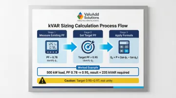
Critical note: Target 0.95–0.97 PF, not unity. Overshooting to 1.0 or into leading territory causes its own problems.
Step 3: Select Placement and Implementation
Placement determines how much of your distribution system benefits from correction. Each option carries a different cost-effectiveness trade-off:
At individual load (motor terminals)
- Most effective at reducing feeder current
- Highest cost per unit of correction
- Best for large, continuously running motors
At group or sub-feeder level
- Practical compromise for clusters of similar loads
- Balances cost and effectiveness
- Simplifies maintenance and monitoring
Centralized at main bus
- Lowest installed cost
- Only corrects upstream—distribution feeders still carry reactive current
- Automatic multi-step banks preferred to handle variable load profiles
Key Factors That Affect Power Factor Correction in Industrial Plants
Non-Linear and Variable Loads
Induction motors running lightly loaded, VFDs, arc welders, arc furnaces, and fluorescent ballasts all degrade power factor through different mechanisms. VFDs introduce harmonic currents that standard capacitor banks cannot correct and can amplify through resonance, making harmonic content a critical input to PFC design.
ValuAdd's IEEE 519-compliant drive systems, such as the Benshaw H2 519/519P series, reduce injected harmonic distortion to less than 8% THDv and 5% TDDi. This keeps correction system design straightforward and protects sensitive downstream equipment.
Harmonic Resonance Risk
Capacitors have falling impedance at higher frequencies, making them vulnerable to carrying amplified harmonic currents when their resonant frequency coincides with a harmonic order present on the network. In plants with significant VFD or rectifier loads, detuned capacitor banks (with a series reactor tuned below the 5th or 7th harmonic) should be specified instead of plain capacitor banks.
Practical threshold: Voltage THD above 5% is a practical threshold for considering detuned banks rather than standard capacitors. Without detuning, resonance can amplify harmonic currents to levels that destroy equipment and distort voltage waveforms beyond IEEE 519 limits.
Operating Condition Variability
Correction system design must account for how plant conditions shift throughout the day and across seasons. Two factors drive most of the variability:
- Ambient temperature affects capacitor life and rated performance
- Load variation across shifts changes reactive power demand significantly
A plant running two shifts of heavy motor load and then sitting idle overnight is a good example. Fixed correction would overcorrect during the low-load period, pushing the system into a leading power factor condition. Automatic stepped banks handle this variability far more effectively.
Soft Starters as a Load-Side Tool
Beyond capacitor banks, the load side of the system offers another lever for reducing reactive demand. Soft starters ramp voltage smoothly during motor starting, cutting inrush current and the associated kVAR spike. For facilities where starting events are frequent or of high kVA magnitude, this can meaningfully reduce the required correction bank size.
ValuAdd's medium voltage soft starter lineup covers these applications directly:
- MVE-P series: 2.3 kV to 15 kV, 110 A to 1200 A
- MVDH series: Medium voltage, designed for demanding drive applications
Common Mistakes and When PFC May Not Be the Right Move
Installation Mistakes to Avoid
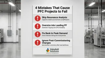
Four installation errors account for most PFC failures in the field:
- Skip resonance analysis with VFDs present — Standard capacitors in harmonic-heavy environments create a resonance trap that amplifies harmonic currents, causing capacitor failure, fuse operation, and voltage distortion.
- Oversize and drive into leading power factor — Overcorrection causes generator tripping, UPS instability, and motor self-excitation. Backup generators often become unstable when leading reactive current exceeds 20% of their rated current. Voltage rise during light-load periods is a secondary consequence.
- Fix bank size to peak reactive demand — When load drops, fixed banks sized for peak demand push the facility into leading PF, creating the same instability problems as overcorrection.
- Ignore plant changes after commissioning — Adding motors, VFDs, or production equipment reshapes the reactive power profile. Re-evaluate the PFC system any time major loads are added or removed.
The Harmonic Misconception
PFC corrects displacement power factor—lagging current from inductive loads—but does nothing to filter harmonic currents generated by non-linear loads. In plants with high THD, active harmonic filters or passive tuned filters must be added separately, or the PFC system must be designed to integrate with them. Installing standard capacitors without a harmonic audit will worsen distortion, not reduce it.
When PFC Is Not the Right First Step
PFC is worth pursuing only when the underlying conditions justify the investment. In three situations, other actions should come first:
- Idling motors driving the low PF — Eliminate idling motors, match motor size to actual load, or replace oversized units before buying correction equipment. Operational fixes cost far less.
- Near the penalty threshold with weak ROI — If the investment won't pay back within 36 months, reallocate the budget to efficiency measures with a stronger return.
- No reactive power charges on your tariff — Small facilities on flat-rate tariffs see no financial benefit from PFC. Confirm your tariff structure before committing to hardware.
Conclusion
Power factor correction supplies reactive power locally so that industrial feeders, transformers, and cables carry less total current—reducing losses, improving voltage, and eliminating utility penalty charges in facilities where inductive motor loads dominate. For most industrial plants, PFC delivers strong ROI with payback periods of 12-36 months.
That said, design must account for the facility's specific load profile, harmonic content, and variability. Blanket installation of capacitor banks without baseline measurement and resonance analysis is the most common reason PFC projects fail to deliver projected savings.
Before committing to a design, follow these three implementation principles:
- Establish an accurate baseline using power monitoring equipment like the Socomec DIRIS B
- Specify detuned banks when voltage THD exceeds 5% to prevent resonance issues
- Target 0.95–0.97 PF rather than unity to avoid overcorrection penalties
Frequently Asked Questions
What is power factor correction in industrial plants?
PFC is the practice of adding capacitive reactive power via capacitor banks or active compensators to offset the inductive reactive demand of motor-heavy loads. This brings the plant's power factor closer to unity, reduces total current drawn from the utility, and eliminates penalties while improving system efficiency.
Why do industrial plants use power factor correction?
Plants use PFC to avoid utility reactive power penalties (which can add 5-10% to electricity bills), reduce I²R losses in cables and transformers, and free electrical system capacity for additional production load without infrastructure upgrades.
What does a power factor of 80% mean?
A PF of 0.80 means only 80% of the current flowing through the plant's electrical system is doing useful work. The remaining 20% is reactive current that causes losses and triggers utility charges but produces no output—correction brings this ratio closer to 100%.
What methods are used for power factor correction in industrial plants?
The main approaches are fixed capacitor banks (constant loads), automatic stepped banks (variable profiles), detuned banks with series reactors (harmonic-heavy environments), and active compensators such as STATCOMs for fast-changing or heavily distorted loads.
How do VFDs and non-linear loads affect power factor correction design?
VFDs and other non-linear loads inject harmonic currents that can cause resonance with standard capacitor banks, amplifying harmonic distortion and damaging equipment. In these environments, detuned or active filter solutions must be used, and harmonic analysis is required before specifying any PFC equipment.
How often should capacitor banks be inspected in industrial plants?
Conduct quarterly visual inspections for bulging, discoloration, or leaks, and perform contactor wear checks and capacitance verification every 12-18 months. Re-measure power factor after any significant load change, such as adding motors, VFDs, or other major equipment.