Introduction
A power failure at a water or wastewater treatment plant isn't just a maintenance problem — it's a public health event. Every stage of treatment, from raw water intake through filtration, chemical dosing, disinfection, and discharge, depends on electrical power. Pumping systems alone account for 86% of all electricity consumption in drinking water utilities and 62% of motor-driven electricity in wastewater facilities, making electrical infrastructure the operational backbone of these plants.
These facilities run 24/7 with no tolerance for downtime. Even brief outages halt finished water production and cause pressure drops that let contaminants enter distribution systems — outcomes regulators and operators can't afford.
The physical environment adds another layer of complexity. Wet wells, chemical exposure zones, hydrogen sulfide in sewage areas, and high-pressure washdown conditions require electrical equipment built to survive corrosive, moisture-laden atmospheres while meeting strict safety standards.
This article explores the core electrical equipment, motor control strategies, automation systems, and environmental protection requirements that define effective electrical solutions for water and wastewater treatment plants.
Key Takeaways
- Water treatment plants consume 1.8% of total U.S. electricity, with pumping systems dominating at 86% for water utilities and 62% for wastewater
- Core infrastructure spans switchgear, motor control centers, VFDs, soft starters, and control panels built for continuous operation
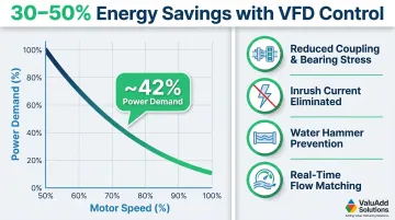
- VFDs deliver 30–50% energy savings in variable-flow pump applications through speed control matched to actual demand
- PLCs, HMIs, and SCADA systems enable remote monitoring and unmanned operation across distributed facilities
- IP65/66/68 and NEMA 4X-rated equipment handles wet, corrosive conditions while meeting NEC, IEEE 519, and OSHA requirements
Why Water & Wastewater Treatment Plants Are Electrically Intensive
The Pumping Energy Reality
Municipal water and wastewater facilities rank among the most electrically demanding industrial operations. Pumping systems consume 86% of all electricity in drinking water utilities and 62% of motor-driven loads in wastewater treatment plants. This concentration of energy use in pump motors makes motor control and power management design decisions with direct consequences for cost and reliability. The sector collectively uses approximately 69.4 billion kWh annually, representing 1.8% of total U.S. electricity consumption.
Non-Negotiable Uptime Requirements
Unlike most industrial facilities that can schedule maintenance downtime, water treatment plants operate under continuous demand. The EPA warns that power loss at drinking water facilities halts finished water production and causes pressure drops that risk contamination entering distribution systems. For wastewater plants, pump failures result in untreated sewage discharges into waterways or backups into residential areas—creating immediate public health emergencies.
Meeting that demand requires electrical systems designed for redundancy, in-service maintainability, and resilience against power quality disturbances. Facilities commonly implement:
- Dual-feed configurations to eliminate single points of failure
- Automatic transfer switches that restore power within seconds
- Modular equipment designs that allow component replacement without a full plant shutdown
Multi-Stage Electrical Loads
Both water treatment plants (WTPs) and wastewater treatment plants (WWTPs) span multiple electrically-driven process stages. A typical wastewater plant moves through six distinct stages:
- Screening and primary sedimentation
- Secondary biological treatment with aeration blowers
- Tertiary filtration
- UV or chemical disinfection
- Sludge handling
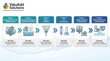
Each stage requires dedicated motor circuits, instrumentation power, control systems, and monitoring equipment—producing complex electrical distribution networks that serve hundreds of individual loads across sprawling facilities.
Core Electrical Equipment in Water & Wastewater Treatment Plants
Power Distribution Infrastructure
Treatment plant electrical systems begin with utility transformer connections that step down transmission voltages to usable levels. Main switchgear or switchboards receive this power and distribute it throughout the facility through panelboards and sub-distribution equipment.
The choice between switchgear and switchboards shapes long-term maintenance flexibility. Switchgear uses draw-out circuit breakers in metal-clad compartments, allowing removal and replacement without de-energizing adjacent sections — essential for plants that can't afford full shutdowns. Switchboards use fixed-mounted breakers in a more compact, lower-cost configuration suited for sites where maintenance windows allow complete de-energization.
Voltage tier selection depends on facility size and motor horsepower. Low-voltage systems (480V in North America) serve motors up to approximately 1,000 HP. Medium-voltage systems (2.4kV to 15kV) become economical for motors above 250 HP, reducing feeder conductor costs through lower current flow and improving efficiency over long cable runs to remote pump stations.
Motor Control Centers (MCCs)
MCCs consolidate starters, overload relays, disconnect switches, and VFD mounting buckets for multiple motors into unified assemblies. This centralization simplifies wiring, reduces installation costs, and creates a single maintenance access point for the pump motors and blowers distributed across a treatment plant.
Modern MCCs incorporate intelligent motor protection relays that monitor current, voltage, power factor, and ground fault conditions. These relays provide early warning of motor degradation, helping crews address problems before they cause unplanned motor failures.
Cables and Wiring in Wet Environments
Cable selection in water and wastewater facilities must address constant moisture exposure, chemical vapors, and physical routing through wet wells and chemical dosing areas. Key considerations include:
- Moisture-resistant insulation rated for wet locations per NEC requirements
- Halogen-free constructions that reduce toxic emissions during fire events
- Direct burial ratings for underground runs between process areas
- Proper conduit fill calculations per NEC Article 430 for motor branch circuits accounting for high inrush currents
Power Factor and Harmonic Management
The same motors and drives that make treatment plants efficient also create power quality challenges. Large motor populations generate inductive loads that degrade power factor, potentially triggering utility penalties. VFD installations compound this by introducing harmonics that can disrupt sensitive instrumentation and violate utility interconnection agreements. IEEE 519-2022 establishes harmonic distortion limits at the point of common coupling (PCC), typically requiring active or passive harmonic filtering in facilities with significant VFD populations.
ValuAdd's VFDs use H-Bridge multi-level technology to meet IEEE 519 compliance directly, delivering less than 8% total harmonic voltage distortion (THDv) and 5% total demand distortion current (TDDi) — without requiring add-on filters in most installations.
Motor Control Solutions: VFDs and Soft Starters for Pump Systems
The Dominant Role of Pump Motors
Raw water intake pumps, chemical feed pumps, aeration blowers, filter backwash pumps, and effluent discharge pumps represent the overwhelming majority of motor loads in treatment plants. How these motors start, stop, and vary speed directly impacts energy costs, mechanical wear, and water hammer risk in piping systems.
Traditional across-the-line starters subject motors to 600-800% inrush current spikes and apply full mechanical torque instantaneously—causing equipment stress, electrical system voltage sags, and hydraulic transients that damage valves and pipe joints.
Variable Frequency Drives for Flow Control
VFDs enable pump motors to operate at variable speeds matched to actual process demand rather than running at fixed full speed with throttle valves restricting flow. The savings follow the pump affinity laws: power consumption varies with the cube of speed, so reducing motor speed to 75% cuts power demand to approximately 42% of full load.
Industry data shows VFD savings of 30-50% in many rotodynamic pump installations, with even higher returns when replacing discharge valve throttling control. These savings compound over the 20-30 year lifespan of treatment plant equipment, often justifying VFD investments within 18-36 months.
VFDs also eliminate hard starts, delivering mechanical and electrical benefits that extend equipment life:
- Reduces stress on couplings, bearings, and seals by removing instantaneous torque application
- Lowers electrical stress on supply systems by avoiding 600-800% inrush current spikes
- Prevents water hammer through programmable acceleration and deceleration ramps
- Enables real-time flow matching, eliminating throttle valve energy waste
ValuAdd's Medium Voltage VFDs use H-Bridge multi-level technology to support motors from 300 HP to 12,000 HP at voltages up to 7.2kV. The near-sine wave output reduces motor heating and acoustic noise—a meaningful advantage in enclosed treatment plant environments where both factors affect long-term reliability.
Soft Starters for High-Inertia Applications
Soft starters serve applications requiring controlled motor acceleration without continuous speed variation. By gradually ramping voltage during startup, soft starters limit inrush current to 200-400% of full load (versus 600-800% for across-the-line starters) while providing smooth torque buildup that protects mechanical components.
Soft starters reduce hydraulic surge transients through controlled pump acceleration, preventing water hammer damage to piping systems. They occupy smaller footprints and cost significantly less than VFDs—making them ideal for constant-speed applications where energy optimization isn't the primary concern.
For large fixed-speed applications like raw water intake pumps, ValuAdd's medium-voltage soft starters support motors up to 25,000 HP at 13.8kV. Class E2 load break compliance ensures safe isolation and bypass during maintenance—an important consideration for pumps that can't afford extended downtime.
Comparing VFDs vs. Soft Starters: Decision Framework
Choose VFDs when:
- Process flow must vary continuously to match changing demand (distribution pumping, variable influent flows)
- Energy optimization justifies higher capital investment (high-runtime applications)
- Soft start/stop alone won't deliver needed operational benefits
Choose soft starters when:
- Motors operate at constant speed with on/off control (fixed-duty intake pumps)
- Primary goal is limiting inrush current and mechanical stress
- Budget or space constraints favor simpler solutions
- Application doesn't require continuous speed variation
The decision often varies by pump function within the same plant: VFDs for variable-demand distribution pumps, soft starters for large fixed-speed raw water intake pumps.
Automation, Control Panels, and SCADA Integration
Electrical Control Panels and PLCs
Modern treatment plant control panels house Programmable Logic Controllers (PLCs) that execute automated process sequences: chemical dosing proportional to flow rates, pump lead/lag rotation to equalize runtime, alarm management, and safety interlocks preventing equipment damage.
Control panels integrate multiple components:
- PLCs with I/O modules connecting to field sensors and actuators
- Human Machine Interfaces (HMIs) for operator visualization and control
- Circuit breakers and power distribution for panel-mounted devices
- Relays and contactors for discrete control functions
- Power supplies providing isolated DC voltage for controls
According to Walchem's control systems analysis, PLCs respond faster than human intervention while executing complex logic consistently—automatically shutting down pumps in proper sequence when suction pressure drops, preventing cavitation damage.
HMI and Operator Interface
HMIs transform abstract sensor data into visual representations operators can quickly interpret: flow rates, pressures, chemical feed rates, pH levels, and turbidity trends. Touch-screen interfaces allow setpoint adjustments, manual overrides during maintenance, and acknowledgment of alarm conditions.
Industrial environments demand ruggedized displays rated for moisture and temperature extremes. ValuAdd's IP68-rated industrial displays deliver 1,200 cd/m² brightness—readable in direct sunlight—and handle continuous water exposure and chemical atmospheres. Models range from compact 7-inch panels for pump stations to 15.6-inch displays for central control rooms.
SCADA Systems for Plant-Wide Monitoring
Supervisory Control and Data Acquisition (SCADA) systems integrate data from all PLCs, sensors, and meters across single or multiple facilities into centralized monitoring platforms. Operators view plant-wide status from single screens, access historical trends for troubleshooting, and receive alarm notifications via text or email.
This becomes especially valuable for utilities managing distributed infrastructure with limited staff. SCADA enables unmanned operation of remote pump stations by pulling data from Remote Terminal Units (RTUs) that continuously transmit:
- Wet well levels and pump status
- Power availability and fault conditions
- Alarm notifications during storm events or off-hours
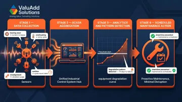
Predictive Maintenance Through Data
The same data SCADA systems collect feeds into predictive maintenance workflows. Modern control systems log motor current signatures, bearing temperatures, vibration levels, and runtime hours continuously. Analytics identify gradual degradation patterns—bearing wear causing slight current increases, seal leaks reducing pump efficiency—enabling scheduled maintenance before catastrophic failures occur. This proactive approach reduces unplanned downtime and extends equipment life while lowering lifecycle costs.
Environmental Protection and Safety Compliance
Hazardous and Wet Environment Ratings
Treatment plants expose electrical equipment to moisture, chemical vapors, hydrogen sulfide in wet wells, and high-pressure washdown conditions. Proper enclosure selection is both a code requirement and essential safety measure.
IP (Ingress Protection) ratings specify dust and water resistance:
- IP65: Dust-tight, protected against water jets (6.3mm nozzle)—suitable for general plant areas with occasional washdown
- IP66: Dust-tight, protected against powerful water jets (12.5mm nozzle)—appropriate for areas with regular high-pressure cleaning
- IP68: Dust-tight, protected against continuous immersion—required for submerged or frequently flooded locations
NEMA ratings provide similar protection with additional environmental testing:
- NEMA 4: Watertight and dust-tight, protects against hose-directed water—suitable for outdoor and indoor wet locations
- NEMA 4X: Adds corrosion resistance to NEMA 4 specifications, exceeding IP66 in some tests—the standard choice for wet, chemically active treatment plant environments
- NEMA 7/9: Designed for hazardous classified locations where explosive gases or dust are present, required in wet wells and digester areas
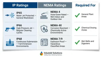
ValuAdd carries components rated IP65 through IP68 and NEMA 4X, covering the full range of enclosure requirements common in water and wastewater applications.
Code Compliance Framework
Treatment plant electrical systems must comply with multiple regulatory standards:
- NEC Article 430: Governs motor circuit conductors, overcurrent protection, controllers, and disconnects
- NEC Articles 500-516: Cover hazardous classified locations where flammable gases like methane and hydrogen sulfide are present
- IEEE 519: Establishes harmonic distortion limits for facilities with large VFD populations
- OSHA 1910.303: Mandates electrical safety requirements including equipment ratings for wet locations and GFCI protection
Several of these codes intersect in wet well and digester applications. Hydrogen sulfide concentrations in these areas trigger hazardous location classifications under NFPA 820, which means explosion-proof equipment or purged/pressurized enclosures are required—not optional. Proper grounding, bonding, and ground-fault protection in wet areas prevent electrocution hazards throughout the rest of the facility.
Redundancy and Power Continuity
Uninterrupted operation depends on layered backup systems working in sequence:
Automatic Transfer Switches (ATS) detect utility power loss, start backup generators, and transfer critical loads within seconds. The EPA recommends ATS installation at all unmanned critical facilities.
Main-tie-main switchgear provides a second layer of protection at the distribution level. Two normally closed main breakers feed separate bus sections, with a normally open tie breaker between them. When one utility feed fails, the dead main opens and the tie closes—restoring power across the entire facility from the remaining source without manual intervention.
Uninterruptible Power Supplies (UPS) bridge the gap between utility loss and generator pickup, typically 10–30 seconds, keeping control systems, instrumentation, and SCADA online. This prevents process upsets and maintains monitoring capabilities during outages.
Frequently Asked Questions
Do water treatment plants need electricity?
Yes, water treatment plants depend entirely on electricity to operate pumps, aeration blowers, chemical dosing systems, filtration equipment, UV disinfection units, and all monitoring and control systems. Without electrical power, treatment processes halt completely, creating public health risks.
What equipment is used in water treatment?
Core equipment includes pumps and blowers driven by electric motors, filtration units, chemical dosing systems, and disinfection systems (UV or chlorination). The electrical infrastructure—switchgear, motor control centers, VFDs, soft starters, control panels, and SCADA systems—powers and controls all these processes.
What is SCADA in water treatment?
SCADA (Supervisory Control and Data Acquisition) is a centralized monitoring and control platform that collects real-time data from sensors and PLCs across a facility. It enables remote management of unmanned sites and supports regulatory data logging, trend analysis, and alarm notification.
What are motor control systems?
Motor control systems are the electrical components—starters, VFDs, soft starters, motor control centers, and protective relays—that start, stop, and regulate electric motors driving pumps and blowers. They prevent electrical faults, reduce mechanical stress, and cut energy consumption.
What are the 7 steps in wastewater treatment?
The typical stages are screening/pre-treatment, primary sedimentation, secondary biological treatment, secondary clarification, tertiary filtration, disinfection, and sludge handling. Each stage relies on electrically powered pumps, aerators, mechanical systems, and instrumentation for proper operation.
What is the difference between STP and WWTP?
STP (Sewage Treatment Plant) specifically processes domestic sewage, while WWTP (Wastewater Treatment Plant) is the broader modern term encompassing all types of wastewater treatment including industrial effluent. Both rely on the same categories of electrical systems and motor control equipment.