Introduction
Plant engineers and system integrators face a persistent challenge: power distribution systems in industrial environments must handle high currents, constant vibration, and thermal cycling — yet rigid connections are the first point of failure. Loose or cracked joints increase resistance, leading to overheating, arcing, and costly unplanned downtime. Faulty electrical connections rank among the leading mechanical failure modes in industrial facilities — and in many plants, they're also the hardest to catch before damage is done.
Copper braids and flexible connectors provide the engineered solution to this problem. By replacing rigid busbars and fixed terminations with multi-strand assemblies that absorb movement and thermal expansion, these components protect critical connection points from stress concentrations that would otherwise compromise electrical integrity.
What follows covers the types available, key performance properties, common industrial applications, and practical selection criteria for long-term reliability.
Key Takeaways
- Copper braids and flexible connectors carry high currents while absorbing vibration and thermal expansion that rigid connections cannot handle
- Available types include braided wire, laminated foil, and flexible busbars — each optimized for different current densities and flexibility requirements
- Low resistance, vibration damping, and thermal compensation reduce failure risk in facilities where unplanned downtime is costly
- Choosing the right connector means matching current capacity, flexibility rating, end-fitting type, and environmental conditions such as corrosion exposure
- Manufacturing, oil and gas, and water treatment operations depend on these connectors to keep power distribution running without interruption
What Are Copper Braids and Flexible Connectors?
Copper braids are assemblies made from multiple fine-gauge, high-purity copper wire strands woven together and terminated with conductive end fittings such as lugs, clamps, or custom terminals. This construction creates a current pathway that remains electrically intact through movement, vibration, and dimensional change. Rather than concentrating mechanical stress at a single rigid joint, the braided structure distributes force across thousands of individual strand contact points.
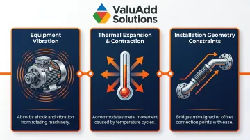
Flexible connectors differ fundamentally from rigid busbars in their ability to accommodate relative motion. Where a solid or laminated rigid busbar transfers power along a fixed path, a flexible connector bridges two points that may shift relative to each other. Common causes include:
- Equipment movement or vibration during operation
- Thermal expansion and contraction through load cycling
- Installation geometry constraints where rigid runs aren't practical
This makes them essential for motor terminals, moving machine components, and connections subject to routine thermal cycling.
The end fitting is as critical as the braided copper body itself. The attachment method — whether crimped, welded, or compression-bonded — determines compatibility with busbars, switchgear terminals, and other connection points. Poor termination quality leads to increased contact resistance, localized heating, and premature failure.
Many manufacturers now specify IEC 61238-1 certified crimping systems, which set rigorous requirements for temperature rise, contact resistance, and mechanical stability under load cycling.
Types of Flexible Copper Connectors for Power Distribution
Not all flexible copper connectors suit the same application. Current density, flexibility requirements, and enclosure constraints each point toward a different construction type.
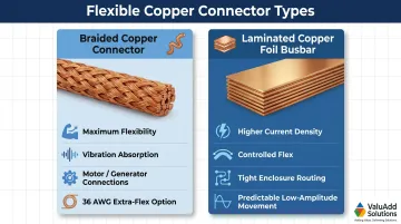
Braided Copper Connectors
Braided copper connectors consist of interlaced fine copper strands that offer maximum flexibility and excellent vibration absorption. This makes them ideal for dynamic connections — motor terminals, generator connections, and moving machine components.
Braid density and strand count control both flexibility and current capacity. Extra-flexible constructions use finer 36 AWG wires to handle severe vibration and misalignment, while standard 30 AWG constructions suit medium-duty applications.
End-fitting options for braided connectors include:
- Lugs for bolt-on busbar connections in switchgear and panels
- Clamp-style fittings for cable tray mounting and grounding straps
- Custom-welded ends for OEM machinery and non-standard terminals
The attachment method affects long-term resistance at the joint. Crimp terminations using IEC 61238-1 certified tooling eliminate voids and reduce resistance variability compared to manual brazing and welding.
Laminated Copper Foil Flexible Busbars
Laminated copper foil busbars use multiple thin copper layers stacked and bonded, offering a lower profile and higher current density in tight enclosures. They are commonly used in switchgear, VFD cabinets, and battery interconnects where space is limited but current demand is high.
The key difference from braided types: laminated foil provides more rigidity with controlled flex compared to braided wire. This makes it preferable for predictable, low-amplitude movement rather than constant vibration or articulation. The minimum bending radius equals the total thickness of the copper layers, allowing tight routing in compact enclosures without degrading electrical performance.
Tinned vs. Bare Copper Construction
Tin plating protects copper strands from oxidation and corrosion, especially in humid, chemical-laden, or coastal environments. Bare copper is susceptible to forming copper oxide, a compound highly resistive to electrical current. Tin acts as a barrier coating, sealing the copper substrate from oxygen and moisture.
The trade-off: tinned connectors have marginally higher contact resistance than bare copper but much longer service life in harsh conditions. ASTM B33 is the standard specification for tin-coated soft or annealed copper wire for electrical purposes, requiring the tin coating to be continuous and firmly adherent. In hazardous areas such as oil and gas facilities, tinned copper is the standard choice to prevent oxidation and maintain joint integrity over time.
Key Performance Properties for Industrial Power Systems
In power distribution, the failure of a single flexible connection can cascade into equipment damage or unplanned downtime. The performance properties of copper braids are engineered specifically to prevent these failure modes.
Low Electrical Resistance
High-purity copper combined with a large cross-sectional contact area from multiple strands minimizes resistive losses. Reduced resistance means less heat generation at the connection point, preserving both the connector and adjacent components. Electrolytic Tough Pitch (ETP) copper (UNS C11000) exhibits a nominal electrical conductivity of 100% to 101.5% IACS (International Annealed Copper Standard), equivalent to 58.108 MS/m at 20°C. This industry-standard material ensures consistent electrical performance across manufacturers.
Vibration and Movement Absorption
The braided structure acts mechanically like a spring network: individual strands deflect independently, distributing mechanical stress across thousands of contact points rather than concentrating it at one rigid joint. This is why braided connectors outperform rigid alternatives in environments with rotating equipment, pumps, compressors, and presses. Vibration from generators and transformers loosens rigid connections, leading to increased resistance, overheating, and arcing — failures that flexible connectors are designed to prevent.
Thermal Expansion Compensation
When conductors, busbars, and connected equipment heat and cool through operating cycles, the cumulative dimensional change can crack or loosen rigid connections over time. The linear coefficient of thermal expansion for copper is approximately 16.8 µm/m·°C. Over a 150°F temperature swing, that translates to roughly 1.728 inches of expansion per 100 feet.
Flexible connectors absorb this movement, keeping connection resistance stable across temperature swings. Engineering guidance dictates that flexible connector length should account for the expected temperature delta in the application to prevent mechanical stress on rigid buswork.
Current-Carrying Capacity and Heat Dissipation
The braided surface area aids thermal management: heat generated by I²R losses dissipates faster from a high-surface-area braided conductor than from a solid conductor of the same cross-section. This allows flexible connectors to carry high currents in compact form factors — a practical advantage for switchgear and control cabinet design where space is constrained.
Manufacturers validate ampacity ratings through temperature-rise testing against established standards, including:
- CEI 60694 — international standard for high-voltage switchgear and controlgear
- IEEE/ANSI C37.34 — test procedures for high-voltage DC air switches
Specifying connectors tested to these standards confirms that published ampacity values reflect real operating conditions, not just theoretical calculations.
Industrial Applications Across Key Sectors
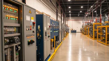
Manufacturing and Processing Plants
Flexible connectors link motor terminals, servo drives, and VFD output connections to the load, absorbing vibration from presses, conveyors, and robotic arms while maintaining stable power delivery. Unplanned downtime in manufacturing averages $260,000 per hour, with automotive plants losing up to $2.3 million per hour. Equipment failure accounts for 42% of all unplanned downtime.
Mechanical vibration loosens rigid electrical connections, leading to increased resistance, overheating, and arcing. Flexible connectors prevent these failures through their vibration-isolating design — making them a practical safeguard in any high-cycle production environment.
Oil, Gas, and Petrochemical Facilities
In oil, gas, and petrochemical facilities, flexible connectors appear in several critical roles:
- Pump and compressor motor connections subject to continuous vibration
- Panel-to-busbar jumpers in classified hazardous areas
- Equipment bonding and grounding for corrosion and arc prevention
Tinned copper construction addresses corrosion directly — the oil and gas industry faces an estimated $1.372 billion in annual corrosion costs. On the regulatory side, NEC Articles 500 and 505 mandate specific grounding and bonding for Class I, Division 1/2 and Zone locations. Internationally, IEC 60079-14 and ATEX Directive 2014/34/EU govern explosive-atmosphere installations, requiring measures to prevent stray currents, corrosion, and sparks.
Municipal Water Treatment
Large pump motors, blowers, and drives operate continuously in humid environments. Flexible connectors at motor terminals and between VFD output busbars and motor leads absorb vibration and accommodate dimensional shifts from thermal cycling. VFD-to-motor connections require careful grounding to mitigate high-frequency bearing currents and electromagnetic interference. ValuAdd serves this sector with flexible busbar solutions and industrial electrical components rated for continuous-duty, high-uptime water treatment applications.
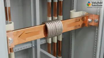
Switchgear, Power Panels, and Substations
Flexible connectors serve as busbar jumpers, phase connectors within switchgear assemblies, and expansion joints between rigid busbar sections. Their flexibility allows compact panel layouts that rigid busbars cannot accommodate — a practical advantage ValuAdd's product portfolio addresses directly for system integrators. IEC 61439-1 dictates that internal connections must be rated for short-circuit loads and must undergo rigorous temperature-rise and dielectric testing. Flexible braids also act as expansion joints, absorbing thermal expansion and vibration at transformer and switchgear connection points.
Selecting and Maintaining Flexible Connectors for Power Distribution
How to Select the Right Connector
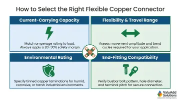
Four primary sizing and specification factors determine the correct connector:
- Current-carrying capacity: Select based on continuous load current plus a safety margin (typically 20-30% above nominal load)
- Flexibility and travel range: Match connector length and braid construction to the expected movement amplitude and direction
- Environmental rating: Specify tinned copper and appropriate insulation for humid, chemical, or outdoor installations
- End-fitting compatibility: Verify termination style and bolt pattern match the connected busbar or terminal
Non-standard applications frequently require custom-engineered connectors. ValuAdd supports OEM machinery and system integrator projects with custom flexible connectors — tailored cross-sections, lengths, and end-fitting configurations specified to match exact installation requirements.
Maintenance and Inspection Best Practices
Visual inspection routine:
- Check for broken strands or fraying at end fittings
- Look for discoloration from overheating
- Inspect for corrosion on copper or terminations
NFPA 70B (2019) recommends inspecting flexible braids annually and replacing any showing signs of corrosion, wear, or broken strands. Periodic resistance measurement using a low-resistance ohmmeter (DLRO) catches degradation before it causes failure — investigate any values deviating more than 50% from the lowest reading among similar connections.
Two critical protection measures extend service life:
- Seal exposed terminations with anti-corrosion compound at copper ends and fitting interfaces, especially in humid or chemically active environments. Conductive electrical contact grease blocks moisture and prevents oxide formation.
- Respect the manufacturer's minimum bend radius — for laminated busbars, this equals the total thickness of copper layers. Exceeding the bend radius fatigues strands prematurely and raises resistance at the bend point.
Frequently Asked Questions
What is copper braid used for?
Copper braid carries electrical current between points that experience relative movement, vibration, or thermal expansion. Common applications include motor terminal connections, busbar jumpers in switchgear, grounding straps, and flexible links in power distribution panels.
What is the purpose of a copper busbar?
A copper busbar is a rigid or semi-rigid conductor that distributes electrical power from a source to multiple circuits or loads within a switchgear assembly, panel, or substation.
What is the best material for a busbar?
Copper is the preferred material for busbars in most power distribution applications due to its superior electrical conductivity (100% IACS minimum for ETP copper), mechanical workability, and long-term reliability. Aluminum is an option where weight is a priority, but requires larger cross-sections to carry equivalent current.
What is the difference between copper braid and a flexible copper busbar?
Copper braid is made from interlaced fine wire strands optimized for maximum flexibility and vibration absorption. A flexible copper busbar (laminated foil type) uses stacked thin copper layers for controlled flex with higher current density in compact spaces. Selection depends on how much movement and vibration the connection must tolerate.
How do you size a flexible copper connector for a power distribution system?
Sizing involves three key steps:
- Match current-carrying capacity to continuous load current, with a 20–30% safety margin
- Select length and braid cross-section to cover the expected movement range
- Specify end fittings that match the terminal geometry of the connected equipment
How long do copper flexible connectors typically last in industrial environments?
Service life varies by environment. In clean, stable installations, connectors typically last 10–20 years; high-vibration or corrosive conditions shorten that range considerably without tinning and corrosion protection. Periodic resistance testing is the most reliable way to catch degradation before failure.