Introduction
Manufacturing lines, water treatment facilities, and oil and gas operations all share a common vulnerability: unplanned electrical downtime. Unplanned downtime costs Fortune Global 500 companies approximately $1.4 trillion annually—equivalent to 11% of their total revenues. In automotive plants alone, a single hour of downtime can reach $2.3 million. When equipment failures account for 42% of these costly stoppages, the components inside your control panel become critical financial assets.
That financial exposure starts with individual components. A failed or improperly selected disconnect switch doesn't just interrupt power—it triggers cascading shutdowns, extends maintenance windows, and puts technicians at risk.
DIN rail mounted disconnect switches are the preferred solution for compact, code-compliant control panel design, offering visible isolation, tool-free installation, space-efficient mounting, and organized power management. This article covers what they are, the critical differences between types, how to select the right specifications, and the compliance standards that protect your operation and your team.
Key Takeaways
- DIN rail disconnect switches snap onto standard rails and provide visible contact separation for reliable circuit isolation in control panels
- Select rotary, fusible, or non-fusible types based on current rating, load break requirements, and overcurrent protection needs
- Class E2 load break switches interrupt full rated current without de-energizing the circuit first, making them required for live switching
- Match NEMA Type 4X (corrosive/washdown) or Type 12 (dust/indoor) ratings to your enclosure environment
- Confirm UL 508A, IEC 60947-3, and NFPA 79 compliance before using in industrial machinery panels
What Are DIN Rail Mounted Disconnect Switches?
A disconnect switch in a control panel serves one essential purpose: it safely isolates a circuit from its power source. This enables maintenance, troubleshooting, or emergency shutoff without de-energizing the entire panel. Unlike circuit breakers that automatically trip on fault current, disconnect switches are manual devices designed for intentional isolation with visible contact separation—a critical requirement for lockout/tagout procedures.
The DIN Rail Foundation
"DIN" stands for Deutsches Institut für Normung (German Institute for Standardization). The 35mm "top-hat" DIN rail, originally governed by EN 50022 and now standardized under IEC 60715:2017, is the universal mounting rail for industrial electrical components.
This rail specification defines two mechanical profiles (35 × 7.5 mm or 35 × 15 mm) and allows components like relays, breakers, and disconnect switches to snap or bolt directly onto the rail without panel cutouts or drilling.
DIN Rail Mounting in Practice
Components designed for DIN rail mounting feature integrated clips or brackets that lock onto the rail. This snap-on system enables dense, organized layouts that reduce wiring complexity and panel footprint. A technician can install a DIN rail disconnect switch in 30–60 seconds versus 5–10 minutes for a traditional panel-mounted device requiring cutouts and drilling.
Disconnect Switch vs. Circuit Breaker
This distinction matters in every panel design:
- Disconnect switch: Provides manual isolation with visible contact separation (IEC 60947-3). Does not protect against overcurrent faults
- Circuit breaker: Automatically interrupts current on overload or short circuit (IEC 60947-2). Does not inherently provide visible isolation
Many motor control applications require both in series: a circuit breaker for fault protection and a disconnect switch for safe maintenance isolation.
Load Break Capability
Not all disconnect switches can safely interrupt current under load. Load break-rated switches (Class E2 per IEC 60947-3) are tested to make and break full rated current without arcing damage. Non-load-break switches must only be operated under no-load conditions.
Using a non-load-break switch on an energized circuit is a common and dangerous mistake that can result in arc flash injuries and equipment damage.
Key Advantages of DIN Rail Mounting in Control Panels
DIN rail systems deliver measurable efficiency gains that directly impact panel cost, installation time, and maintenance downtime.
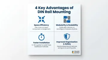
Space Efficiency
DIN rail components occupy a fraction of the space required by panel-mounted devices. A standard DIN rail module is 17.5mm wide versus 48mm (plus clearance) for traditional panel-mounted switches—a 3.6x improvement in space utilization. This allows system integrators to downsize enclosures, reduce material costs, and fit more functionality into existing panel footprints.
Modularity and Scalability
Components snap on and off the rail without rewiring the entire panel. This matters for flexible or upgradeable control architectures where additional circuits, relays, or disconnect switches must be added post-commissioning. A technician can insert a new disconnect switch between existing components in minutes, compared to hours of rework with traditionally mounted hardware.
Faster Installation and Maintenance
DIN rail mounting reduces installation time by 6-10x compared to traditional panel mounting. Snap-on installation eliminates drilling, panel cutouts, and alignment adjustments. Standardized wiring terminals further accelerate connection. During maintenance, components can be removed and replaced tool-free, reducing repair downtime by 80-90%.
Improved Organization and Safety
Grouped, labeled disconnect switches on a DIN rail make it easier for technicians to identify and isolate specific circuits quickly. This visual organization reduces human error during emergency shutdowns and maintenance lockout/tagout procedures. When every second counts during a LOTO compliance check, clear circuit labeling and tool-free removal make the difference between a controlled isolation and a costly delay.
Types of DIN Rail Disconnect Switches
Rotary Disconnect Switches
Rotary disconnect switches use a rotating handle mechanism (typically 90° or 120°) to operate internal contacts. The handle position provides clear visual indication of circuit status—OFF (open), ON (closed), and often a padlockable position for safety compliance. These switches are ideal for:
- Main power isolation at panel entry points
- Branch circuit control in motor control centers
- Manual emergency shutoff applications
Typical current ratings range from 16A to 100A, with 3-pole and 4-pole configurations for three-phase systems. Higher-rated models (400A to 1000A) are available for main disconnects in large control panels.
Fusible vs. Non-Fusible Disconnect Switches
Fusible disconnect switches integrate fuse protection directly into the switch body, combining isolation and overcurrent protection in a single device. They accept standard cylindrical fuses (14x51mm or 22x58mm) and provide high breaking capacity up to 100 kA. Use fusible switches when:
- Branch circuits require both isolation and short-circuit protection
- Space constraints prevent separate breaker and disconnect installation
- Variable frequency drives or other sensitive loads require current-limiting protection to meet SCCR (short-circuit current rating) requirements
Where fusing isn't needed at the disconnect itself, non-fusible switches provide isolation only. Per UL 508A and NFPA 79, overcurrent protection is required but does not have to be integral to the disconnect. A common arrangement uses a non-fused UL 98 motor-rated disconnect as the main switch, with branch-circuit fuses on the load side.
Load Break vs. No-Load Disconnect Switches
IEC 60947-3 defines two load break classes that determine maintenance requirements and operational lifespan:
| Class | Maintenance Required | Switching Capability |
|---|---|---|
| E2 | None throughout service life | Full load switching — thousands of operations |
| E1 | Periodic maintenance required | Full load switching — limited operations |
Class E2 is the higher-performance standard. For most industrial control panel applications where switching under load is expected, E2-rated devices are the appropriate choice.
⚠️ Safety Warning: Never use a no-load-break switch on a circuit that may be energized during switching. Breaking inductive loads — motors, transformers — without arc suppression creates arc flash risk. Always confirm the load break class on the product datasheet before installation.
Selecting and Installing the Right DIN Rail Disconnect Switch for Your Control Panel
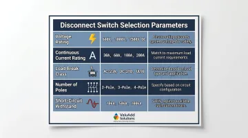
Primary Selection Parameters
Five parameters drive the selection decision. Use this table as a quick-reference guide, then verify each value against your system documentation before specifying.
| Parameter | Typical Values | Key Guidance |
|---|---|---|
| Voltage Rating | 415V, 600V, 800V AC; DC-rated for solar/battery | Match system voltage with safety margin; DC applications require DC-rated switches with appropriate interrupting capability |
| Continuous Current Rating | 16–32A (branch circuits), 63–100A (motor loads), 160–400A (panel mains) | Size at 125% of maximum continuous load current to prevent overheating |
| Load Break Class | Class E2 | Required whenever the switch may be operated under load — motor circuits, process equipment, emergency stop applications |
| Number of Poles | 2-pole, 3-pole, 4-pole | 3-pole for three-phase; 4-pole when neutral switching is required; 2-pole for single-phase or DC |
| Short-Circuit Withstand | 5 kA, 10 kA, 25 kA | Must meet or exceed available fault current at the installation point; add current-limiting fuses upstream if the switch rating falls short |
Enclosure and Environmental Compatibility
Once you have your electrical parameters, match the switch to the physical environment. Enclosure type determines which switch ratings are acceptable.
NEMA Type 4X enclosures provide watertight, dust-tight, and corrosion-resistant protection — mandatory for food processing, chemical plants, and outdoor installations. NEMA Type 12 enclosures suit indoor manufacturing floors where circulating dust, falling dirt, and dripping water are the primary concerns.
The disconnect switch rating must match or exceed the enclosure rating. ValuAdd's disconnect switches carry UL Listed certification with NEMA 4X/12 compliance, so system integrators get documented compatibility without chasing separate verification. When using rotary handles that penetrate the enclosure door, confirm the handle assembly maintains the enclosure's NEMA rating — this is a common oversight during panel builds.
Installation Best Practices
Before mounting:
- Verify complete de-energization using a voltage tester on all poles
- Confirm the DIN rail is clean, free of burrs, and securely fastened to the enclosure backplane
- Check that the rail profile matches the switch mounting specification (35mm standard)
During installation:
- Snap or bolt the switch onto the rail following manufacturer instructions
- Use calibrated torque screwdrivers or torque wrenches for terminal connections—over-tightening damages terminals, under-tightening causes overheating
- Follow busbar and accessory compatibility guidelines in the product documentation
- Maintain proper spacing between adjacent switches for heat dissipation
After installation:
- Label each disconnect per NEC Article 110.22 and NFPA 79 requirements with clear circuit identification
- Verify proper operation by cycling the switch through OFF-ON positions before energizing
- Document the installation, including switch model, current rating, and protected load
Safety Standards and Certifications to Look For
UL 508A (Industrial Control Panels)
UL 508A governs the construction and certification of industrial control panels in North America. Panels must use UL-recognized or UL Listed components, including disconnect switches. Key requirements:
- Main disconnect clearly marked and padlockable in the OFF position
- Multi-source panels require all incoming feeders identified on the nameplate
- Disconnect must be rated for the panel's short-circuit current rating (SCCR)
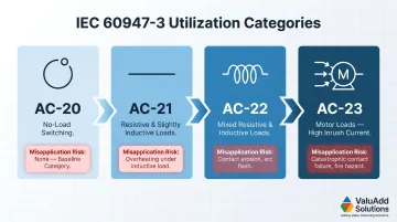
IEC 60947-3 (Switches and Disconnectors)
This international standard applies to switches, disconnectors, and switch-disconnectors up to 1,000V AC or 1,500V DC. It defines utilization categories that dictate device performance:
- AC-20: No-load switching
- AC-21: Resistive loads
- AC-22: Mixed resistive/inductive loads
- AC-23: Motor loads with high inrush currents
Selecting the wrong utilization category for your load type can cause premature contact wear, nuisance tripping, or device failure — so verify this specification before purchasing.
NFPA 79 (Industrial Machinery Electrical Standards)
NFPA 79 requires that machine supply disconnects be:
- Clearly marked and identified
- Padlockable in the OFF position independent of door position
- Interlocked with the enclosure door so the door cannot open while energized
When specifying disconnects for NFPA 79 compliance, confirm that the device carries Class E2 load-break certification and is compatible with the enclosure's door-interlock hardware.
CE Marking (EU and Export Applications)
For European markets or export applications, CE marking involves several overlapping requirements:
- Low Voltage Directive 2014/35/EU: Applies to electrical equipment; EN IEC 60947-3:2021 is a harmonized standard providing presumption of conformity
- Conformity assessment: Manufacturer must compile technical documentation and affix the CE marking
- Machinery Directive 2006/42/EC: Governs final assembly when the disconnect is integrated into a machine
Additional Certifications
Halogen-Free Ratings
For enclosed or confined installations where toxic smoke is a concern, look for halogen-free certification. IEC 60754-1 determines the amount of halogen acid gas evolved during combustion, while IEC 60754-2 measures acidity and conductivity of flue gases. Halogen-free components reduce health hazards during fire events.
IP Ratings
In addition to NEMA ratings, look for IP (Ingress Protection) ratings where additional protection is needed beyond the enclosure. IP65 (dust-tight, water jet protected) and IP68 (dust-tight, continuous immersion) ratings provide extra assurance for harsh environments.
Frequently Asked Questions
What is the purpose of a disconnect switch?
A disconnect switch safely isolates a circuit or piece of equipment from its power source, enabling maintenance or emergency shutoff without de-energizing the entire system. It provides visible contact separation required for lockout/tagout compliance.
What is a DIN rail switch?
A DIN rail switch is any switching device (disconnect, circuit breaker, relay, or contactor) designed to mount on a standardized 35mm DIN rail inside an electrical enclosure or control panel, enabling organized, tool-free installation.
What does DIN rail mean?
DIN rail refers to a standardized metal mounting rail defined by IEC 60715 (formerly EN 50022), universally used in electrical panels worldwide. The name comes from the German Institute for Standardization (Deutsches Institut für Normung).
What does DIN rail mounting mean?
DIN rail mounting means securing electrical components onto a DIN rail using integrated snap-in clips or brackets. The standardized form factor keeps panels organized, simplifies component replacement, and reduces wiring errors during commissioning.
What is a DIN rail connector?
A DIN rail connector (or terminal block) is a wiring device mounted on a DIN rail that connects and organizes conductors. Terminal blocks are distinct from switching devices but used alongside disconnect switches, relays, and breakers in control panels.
What is a DIN circuit breaker?
A DIN circuit breaker is an overcurrent protection device designed to mount on a DIN rail. It automatically trips on fault current, distinguishing it from a disconnect switch, which serves as a manual isolation device without automatic protection.
Correct disconnect switch selection prevents unsafe isolation gaps and unplanned shutdowns. Whether designing new control panels or upgrading existing ones, verify compliance certifications, confirm load break ratings match your application, and check enclosure ratings against your environment. ValuAdd carries UL Listed, Class E2-compliant disconnect switches with NEMA 4X/12 ratings — and the technical staff to help system integrators match the right switch to the job.