Despite being everywhere, fuses are frequently misapplied. Engineers select ratings based on habit rather than load characteristics. Maintenance teams replace blown fuses without diagnosing root causes. The distinction between fast-blow and time-delay types gets overlooked. The result is either nuisance interruptions that halt production or, worse, inadequate protection during a real fault.
This guide breaks down how electrical fuses actually work — the physics, the operational stages, the critical characteristics, and the selection logic that determines whether a fuse protects your system or fails it.
Key Takeaways
- A fuse is a sacrificial overcurrent device wired in series — when current exceeds the rated threshold, its metal element melts and permanently opens the circuit
- Operation is purely thermal: excess current builds I²R heat in the element until it melts, clearing hard faults in fractions of a second
- Three characteristics define suitability: rated current, breaking capacity, and response time class
- Fast-blow fuses protect sensitive electronics; time-delay fuses handle motor and transformer startup inrush without nuisance tripping
- Industrial fuses outperform breakers where response speed, high breaking capacity, and compact footprint are priorities
What Is an Electrical Fuse?
A fuse is a passive electrical safety device installed in series in a circuit, containing a fusible metal element precisely sized to melt and create an open circuit when current exceeds the rated threshold. Its purpose: protect wiring, equipment, and connected systems from the damaging effects of overcurrent.
Electrical circuits are exposed to three types of dangerous overcurrent events:
- Short circuits — immediate, high-magnitude faults where current takes an unintended low-resistance path
- Sustained overloads — prolonged current above the circuit's rated capacity
- Ground faults — current flowing through an unintended path to ground or grounded equipment
A fuse addresses all three by acting as an automatic disconnect — removing the fault from the system without any operator intervention required.
What a Fuse Is Not
A fuse is not a switch, and it is not reusable. Unlike a circuit breaker, it cannot be reset after operating and only senses overcurrent, not voltage anomalies independently.
Two standards define the boundaries of industrial fuse application. UL 248-1 covers low-voltage fuses rated 1,000 V or less with interrupting ratings up to 300 kA. IEC 60269-1 covers enclosed current-limiting fuse-links for AC circuits up to 1,000 V and DC up to 1,500 V, with a rated breaking capacity of at least 6 kA.
Both specifications reach well beyond the consumer fuses most people are familiar with. Circuit breakers dominate residential contexts, but in industrial applications where response speed and high breaking capacity are design requirements, fuses remain the preferred solution.
How Does an Electrical Fuse Work?
A fuse operates through a defined thermal sequence — from the moment overcurrent begins flowing, through element heating and melting, to arc extinction and final circuit interruption. Each stage is governed by the fuse's physical design and the nature of the fault.
Initiation: Responding to Overcurrent
A fuse has no mechanical trigger or electronic sensor. It sits continuously in the live current path and responds passively to thermal conditions. What determines how fast it responds is the magnitude of the overcurrent.
This is the inverse-time characteristic at work:
- A modest overload at 1.25× rated current may take minutes to heat the element to its melting threshold
- A conventional fusing current at 1.6× rated (per IEC 60269 gG guidance from Mersen) operates within 1 to 4 hours
- A bolted short circuit at many multiples of rated current clears in milliseconds — Eaton documents current-limiting operation above fault thresholds clearing in less than 0.008 seconds
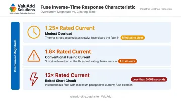
This variable response time is a deliberate design feature, not a limitation. It allows fuses to ignore temporary normal transients while responding aggressively to destructive faults.
Core Operation: Melting and Arc Extinction
Excessive current flowing through the fuse element generates heat proportional to I²R — current squared times resistance. As the element heats toward its melting point, resistance increases, which accelerates further heating. The element melts and separates.
Element materials — silver, copper, and zinc alloys depending on the fuse type — are selected along with element geometry to set the precise thermal threshold that defines the fuse's rating. The notching and mass of the element determine where and how quickly it opens.
Melting the element alone doesn't interrupt the circuit — an electrical arc may form across the gap, and if it isn't extinguished, current continues to flow. Fuse construction addresses this directly:
- Sand-filled bodies (HRC and semiconductor fuses) use silica or quartz sand to absorb arc energy and cool the element
- Non-combustible ceramic or glass housings contain the arc in smaller cartridge fuses
- Medium-voltage fuses may use additional arc-extinction media
A fuse's interrupting (breaking) capacity rating directly reflects its ability to safely extinguish arcs at maximum fault current levels. Exceeding this rating is a serious safety hazard — the fuse body can rupture.
Output: The I²t Value and What It Means
The end result of a fuse operation is a permanent open circuit that fully isolates the faulted section from the supply.
The critical output metric for industrial system design is I²t — measured in ampere-squared-seconds. It represents the total energy let through by the fuse before it clears the fault.
- Melting I²t: minimum energy required to melt the fuse element
- Clearing I²t: melting I²t plus arcing I²t — the total energy delivered to the fault
A lower clearing I²t means less energy reaches downstream components. For variable frequency drives, power semiconductors, and motor windings, this difference determines whether the equipment survives the fault.
Manufacturers publish both values for fuse coordination studies. Per Eaton, a fuse's total I²t must be less than the I²t withstand capability of the semiconductor device it protects.
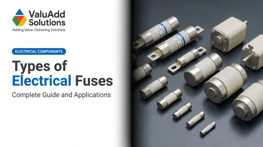
Types of Electrical Fuses and How to Select the Right One
Fuse type selection is not interchangeable. Each type addresses a specific fault profile and load behavior — getting this wrong causes either nuisance trips or failed protection.
Fast-Blow (Quick-Acting) Fuses
Fast-blow fuses interrupt overcurrent with minimal delay. They are designed specifically for circuits where even a brief overcurrent event causes irreversible damage:
- Power semiconductors (diodes, SCRs, IGBTs)
- Instrumentation and PCB-level circuits
- Sensitive control electronics
These are not suitable for motor circuits. A fast-blow fuse will open on every motor start due to startup inrush current — before any actual fault has occurred.
Time-Delay (Slow-Blow) Fuses
Time-delay fuses include a built-in delay that allows short-duration current surges above rated value while still responding to sustained overloads and short circuits. This behavior is essential for motor circuits.
AC motors typically draw locked-rotor current of 4 to 8 times their normal operating current during startup, sustained for several seconds. Without time-delay behavior, that inrush would blow the fuse on every start — before any real fault occurs.
NEC 430.52 governs sizing for motor branch circuits: dual-element time-delay fuses for most squirrel-cage motors are rated at a maximum of 175% of full-load amperage for short-circuit and ground-fault protection. Standard (non-time-delay) fuses are permitted up to 300% FLA under the same code section.
These fuses are standard in motor branch circuits, compressor circuits, and transformer primaries.
HRC (High Rupture Capacity) Fuses
HRC fuses use a sand-filled cartridge body with ferrule or blade contacts. The silica sand quenches the arc by absorbing energy during the arcing phase, enabling these fuses to safely interrupt very high fault currents.
Modern current-limiting industrial HRC fuses commonly carry interrupting ratings of 200,000 A or 300,000 A — and Eaton notes these high interrupting ratings are available at no extra cost in many applications. They are used where prospective short-circuit current is highest:
- Main distribution boards
- Industrial switchgear
- Transformer stations and substations
In many industrial facilities, regulations require qualified personnel to replace HRC fuses — both for safety and to ensure the correct replacement is installed.
Current-Limiting Fuses
Current-limiting fuses open in less than one full AC cycle, limiting the total let-through energy to a fraction of what a standard fuse passes. This is not just faster operation — it fundamentally changes the energy exposure to downstream equipment.
IEC utilization category aR specifically defines partial-range short-circuit protection for power semiconductors. These fuses are the required protection type upstream of:
- Variable frequency drives
- Soft starters
- Rectifier assemblies
- Power semiconductor modules
For applications involving VFDs, soft starters, or semiconductor modules — where I²t coordination is critical — ValuAdd's technical specialists can work through fuse selection during the engineering phase to ensure the right protection class is specified from the start.
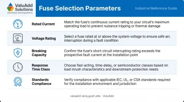
Five Selection Parameters to Verify
Before specifying any fuse, confirm all five:
| Parameter | What to Check |
|---|---|
| Rated current | Match to load; apply derating for ambient temperature above standard |
| Voltage rating | Must meet or exceed system voltage |
| Breaking capacity | Must exceed maximum prospective fault current at the installation point |
| Response time class | Match to load type — fast-blow, time-delay, or current-limiting |
| Standards compliance | UL 248 (North America) or IEC 60269 (international) |
Where Electrical Fuses Are Used in Industrial Operations
Motor Circuit Protection
In motor branch circuits, fuses provide short-circuit protection for conductors and motor windings — upstream of the motor starter and contactor. This coordinates with the overload relay, which handles sustained overload protection separately.
The fuse clears high-magnitude faults fast. The overload relay manages slow thermal overloads. Each device covers a job the other cannot.
Time-delay fuses are the standard choice for this role. A fast-acting fuse will interpret normal motor startup inrush as a fault and open the circuit before the motor reaches running speed. Misapplied fuse speed or sizing causes nuisance opening during motor starting — a preventable source of production interruption.
VFD Input Circuit Protection
VFDs contain IGBTs and rectifier diodes that are among the most fault-intolerant components in an industrial electrical system. A high-energy fault event that might only damage wiring in a standard branch circuit will destroy a VFD's power stage in milliseconds.
Standard branch circuit fuses are not adequate for VFD input protection. ABB's drive protection documentation specifies that semiconductor fuses are required for certain ACS880 drive configurations. Yaskawa publishes input fuse selection tables based on drive input I²t requirements. The fuse must be matched to the drive's published I²t withstand capability — not just the input amperage.
For every VFD installation, refer to the drive manufacturer's fuse specification table. Current-limiting semiconductor fuses at the drive input are the correct protection class for this application.
Transformer and Substation Protection
Medium-voltage fuses protect distribution transformers, capacitor banks, and substation equipment in industrial facilities. Eaton's medium-voltage fuse catalog covers E-rated current-limiting fuses for transformer and feeder protection, with ratings spanning 5.5 kV and current ratings from 10 to 900 A.
A properly sized fuse protecting a distribution transformer costs far less than transformer replacement — and far less than the production downtime a failure causes. HRC fuses in metal-enclosed switchgear provide the high interrupting capacity needed at the transformer primary, where prospective fault current levels are highest.
Control Panel and Instrumentation Circuit Protection
Miniature cartridge fuses protect individual control circuits, PLCs, sensors, and field instrumentation where the panel design and component listings call for fused protection. In 24 VDC control circuits, these fuses prevent a component fault from propagating upstream and affecting unrelated circuits.
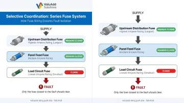
The critical design principle here is selective coordination — in a series of fuses from the supply to the load, only the fuse closest to the fault should clear. This isolates only the affected circuit without disrupting the upstream distribution.
Poor coordination in control panels can cause full system shutdowns from a single component fault. Eaton's guidance on NEC 240.12 selective coordination notes that larger upstream ampere ratings alone do not prove selectivity — coordination must be verified using time-current characteristic curves for the specific fuses installed.
Socomec's RMS Modular Fuse Holders, available through ValuAdd, support high breaking capacity fuses up to 100 kA rms and are certified to UL 4248-1, CSA C22.2, and IEC 60269 standards — making them suitable for industrial panel applications in both North American and international installations.
Frequently Asked Questions
What is an electrical fuse?
A fuse is a passive, sacrificial overcurrent protection device installed in series with a circuit. It contains a metal element engineered to melt when current exceeds a safe threshold, permanently opening the circuit and protecting downstream wiring and equipment from fault damage.
What is the difference between a breaker and a fuse?
Both interrupt overcurrent, but a fuse is a one-time sacrificial device that clears high-magnitude short circuits faster than most mechanical breakers (current-limiting fuses can open in less than 0.008 seconds). A circuit breaker is resettable, though it must be rated for its own interrupting and current-limiting performance. In industrial applications, fuses are often preferred where clearing speed, high breaking capacity, and compact panel footprint are priorities.
Do I need an electrician for a blown fuse?
Standard plug or cartridge fuses in residential settings can often be replaced by a homeowner, but industrial or commercial environments involving HRC, medium-voltage, or high-current fuses typically require qualified personnel by regulation. More critically, a blown fuse should always trigger a root cause investigation before replacement.
What causes a fuse to blow repeatedly?
Two main causes: the fuse is undersized for the actual load (including inrush or overload conditions), or there is a persistent fault in the circuit that the fuse is correctly responding to — an intermittent short, failing equipment, or insulation breakdown. Replacing the fuse without diagnosis leaves the underlying fault unresolved.
What is the difference between fast-blow and slow-blow fuses?
Fast-blow fuses interrupt overcurrent with minimal delay and are used to protect sensitive electronics and semiconductors where brief overcurrent causes irreversible damage. Slow-blow (time-delay) fuses tolerate temporary current surges above rated value — essential for motor, compressor, and transformer circuits where startup inrush would otherwise cause nuisance blowing on every start.
How do I choose the right fuse rating for a motor circuit?
Select a time-delay fuse to handle startup inrush, sized to the motor's full-load amperage. NEC 430.52 sets a maximum of 175% FLA for dual-element time-delay fuses on most squirrel-cage motors. Also confirm the fuse's breaking capacity exceeds the prospective short-circuit current at the motor circuit's point of installation.