Introduction
OEM panel builders face high-stakes decisions at the design stage: undersizing a fused disconnect risks failed UL 508A inspections, voided equipment listings, and costly field failures. Oversizing can mask real fault conditions and reduce protection effectiveness. According to UL 508A compliance data, insufficient Short-Circuit Current Rating (SCCR) is the leading cause of inspection failures—stemming from incorrect disconnect and fuse selection.
This guide gives panel builders a practical sizing framework — whether you're designing a single motor control panel or a complex multi-circuit assembly. You'll walk away knowing how to:
- Read nameplates correctly for accurate load calculations
- Apply the 125%/80% continuous load rule without guesswork
- Maintain SCCR compliance from the first design pass
- Select the right fuse class for your application
- Avoid the most common mistakes that trigger failed inspections
Key Takeaways
- A fused disconnect switch combines load-break isolation with overcurrent protection in one UL-listed device, satisfying both functions in a single component
- Size the disconnect at or above the equipment's Minimum Circuit Ampacity (MCA) and never exceed the Maximum Overcurrent Protection (MOP) rating
- Apply the 125% continuous load rule for loads running 3+ hours; both fuse and switch ampacity must account for this derating
- Select fuse class carefully — it determines interrupting rating (AIC), time-current behavior, and your panel's overall SCCR
- Always verify the disconnect's SCCR against available fault current at the panel's line terminals before finalizing selection
What Is a Fused Disconnect Switch?
A fused disconnect switch is a UL-listed enclosed safety switch that provides two critical functions in a single device: manual load-break isolation (a visible, lockable OFF position) and overcurrent/short-circuit protection through replaceable fuses. This dual-function design distinguishes it from a non-fused disconnect or standalone circuit breaker.
Key Internal Components
Understanding the internal architecture helps OEM builders match devices to panel requirements:
- Load-break contact mechanism - Rated for the switch's full ampere and horsepower rating, designed to safely interrupt load current
- Fuse holders - Accept a specific fuse class and ampere range, with rejection features preventing wrong-class substitution
- Enclosure with NEMA rating - Must match panel voltage, phase, and environmental classification
All components must be matched to your panel's specifications. A mismatch in any element creates a listing violation or field failure risk.
Why OEM Panel Builders Specify Fused Disconnects
Fused disconnects provide a single-device path to meeting both NEC Article 430/440 motor disconnect requirements and UL 508A panel SCCR requirements. That single compliance checkpoint matters when managing third-party listing documentation across complex panels.
For panels serving multiple loads, consolidating into one device delivers tangible advantages:
- Reduces total component count and BOM complexity
- Consolidates two safety functions into one inspection point
- Cuts installation labor and design time on multi-load panels
Key Sizing Factors for OEM Panel Builders
Sizing errors at this stage are the primary reason panels fail third-party listing inspections or generate field callbacks. Five factors connect nameplate data to a compliant, buildable selection.
Factor 1: Equipment Nameplate — MCA and MOP
The equipment nameplate is always your starting point. Two values drive every sizing decision:
Minimum Circuit Ampacity (MCA) sets the floor for both conductor sizing and disconnect switch ampere rating. The disconnect must be rated at or above the MCA. This value accounts for continuous operation and is calculated as 125% of the largest motor's FLA plus the sum of other loads.
Maximum Overcurrent Protection (MOP) sets the absolute ceiling for fuse ampere rating. Exceeding MOP voids the equipment listing—no exceptions.
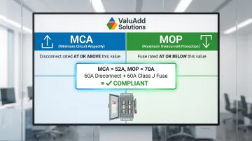
For example, a VFD nameplate showing MCA = 52A and MOP = 70A means: the disconnect switch must be rated ≥52A and the fuse must be ≤70A. A 60A disconnect with 60A Class J fuses satisfies both requirements.
For panels serving multiple load types, repeat this process per load. Document each calculation in your panel build records.
Factor 2: Continuous Load Rating and the 125% Rule
When a load operates for 3 or more hours continuously, both fuse rating and disconnect switch ampacity must be sized to at least 125% of the continuous load current. This is the origin of the "80% rule" for fuses—devices must not be loaded above 80% of their rating.
A 40A continuous motor load therefore requires:
- Minimum fuse rating: 50A (40A × 1.25)
- Minimum disconnect rating: 50A
Ignoring this rule is the most common single cause of thermal overload issues found during inspections. NEC 210.19(A)(1) and 210.20(A) mandate this sizing for all branch circuits.
Factor 3: Available Fault Current and SCCR
The disconnect switch and fuse combination must have a Short-Circuit Current Rating (SCCR) equal to or greater than the available fault current at the panel's line terminals. Available fault current is determined by upstream transformer kVA and impedance—not by load size.
OEM builders must request this value from the end customer or Authority Having Jurisdiction (AHJ) before finalizing selection. Assuming fault current without documentation is a primary source of failed inspections.
Current-limiting fuses (Class J, RK1) can dramatically raise a panel assembly's SCCR, often allowing lower-rated components to remain in the assembly. A feeder circuit with Class J fuses can protect a motor starter with a 5 kA standard SCCR, raising the combination rating to 100 kA or more—provided the fuse's peak let-through current is lower than the component's withstand rating.
Research UL 508A component combination tables or published SCCR tables for specific fuse and switch pairings before finalizing your design.
Factor 4: Voltage Rating and Pole Configuration
Voltage rating must meet or exceed system voltage. Common OEM panel voltages include 240V, 480V, and 600V AC; 24–600V DC for control circuits. AC-rated switches must never be substituted for DC-rated applications—AC interrupting ratings do not transfer to DC applications due to different arc extinction characteristics (DC has no zero-crossing).
Pole selection:
- 2-pole for single-phase loads
- 3-pole for three-phase motor and equipment loads
- 4-pole when the neutral must also be switched
Misapplying a 2-pole switch on a 3-phase circuit leaves one phase unprotected and uninterrupted, creating both a safety hazard and a listing violation.
Factor 5: Load Type and Its Impact on Sizing
Load type directly affects both the disconnect's horsepower (HP) rating requirement and fuse selection:
Motors require a disconnect switch with an adequate HP rating per NEC 430.109—not just an ampere rating. Time-delay fuses are essential to survive high inrush currents (6–10× FLA) at startup without nuisance blowing.
Variable Frequency Drives (VFDs) typically specify a maximum fuse class and size on their nameplate to maintain their own SCCR. Exceeding that rating can void VFD warranty and listing.
Resistive loads (heaters, lighting) follow simpler sizing rules: 125% of load current for continuous operation.
A panel serving mixed load types needs fuse class decisions made per-circuit, not globally.
Selecting the Right Fuse Class for OEM Panel Applications
Fuse class controls three things that directly affect panel design: physical interchangeability (rejection features prevent wrong-class substitution in the field), time-current behavior (fast-acting vs. time-delay), and interrupting rating (AIC). Get this selection wrong and you're either undershooting fault protection or creating nuisance trips that generate field callbacks.
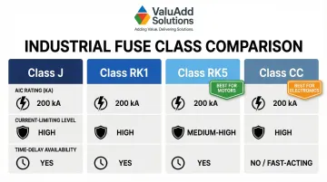
Common Fuse Classes for Industrial OEM Panels
| Fuse Class | AIC Rating | Current Limiting | Time Delay Available | Best-Fit OEM Application |
|---|---|---|---|---|
| Class J | 200 kA | High | Yes | VFDs, high-fault-current panels, motor branch circuits |
| Class RK1 | 200 kA | High | Yes | Motor branch circuits, feeder circuits, high SCCR panels |
| Class RK5 | 200 kA | Moderate | Yes | Motor loads with inrush, general industrial circuits |
| Class CC | 200 kA | High | Yes | Control circuits, low-ampere branch circuits (<30A) |
Fuse Class and Panel SCCR Under UL 508A
Current-limiting fuse classes (J, RK1) reduce let-through current during a fault, which can "boost" the SCCR of downstream components in the panel assembly. This is how OEM builders legally achieve high SCCR ratings without replacing every component in the panel.
Critical requirement: This must be validated against published component combination data, not assumed. Consult UL 508A Supplement SB and manufacturer-published SCCR tables.
That same current-limiting behavior also affects how fuses respond to inrush — which makes time-delay vs. fast-acting selection the next decision after class.
Time-Delay vs. Fast-Acting Selection Logic
Use time-delay fuses when:
- Motor and transformer loads have high inrush (6–10× FLA at start)
- You need to avoid nuisance blowing during normal operation
- The load type is inductive with high starting current
Use fast-acting current-limiting fuses when:
- Protecting sensitive electronics like PLC power supplies or VFD input sections
- You need to clear faults before damage propagates
- The load is resistive or has minimal inrush
Putting a fast-acting fuse on a motor circuit is the most common mismatch in OEM panels — the fuse clears on the first start under inrush, before any real fault exists.
Common Sizing Mistakes OEM Panel Builders Must Avoid
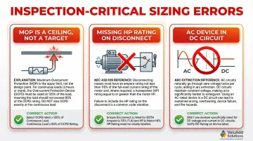
Three Inspection-Critical Sizing Errors
Fusing to MOP instead of treating it as a ceiling. MOP is the maximum permitted value—not the design target. Apply the 80% continuous load rule first, then confirm you haven't exceeded MOP. Fuses sized exactly at MOP with no derating margin violate the 125% continuous load rule.
Overlooking the HP rating on disconnect switches. A switch that's ampere-rated for the load can still be undersized for motor HP under NEC 430.109, which causes listing failure. Verify both ampere and HP ratings whenever motor loads are involved.
Using AC-rated devices in DC circuits. AC interrupting ratings do not transfer to DC applications because DC arcs behave fundamentally differently. Devices used in DC circuits must be explicitly marked for DC use—anything else is both a code violation and a safety hazard.
The "Same Class, Wrong Amp" Substitution Hazard
These three errors typically show up at inspection time. A subtler failure mode, however, happens after the panel ships.
When field technicians replace blown fuses, they often grab the nearest available amp rating rather than the engineered value. One step higher can raise let-through energy enough to damage VFD input stages or push an adjacent component past its SCCR rating.
Recommended practice:
- Document fuse class and amp rating on the panel label
- Include spare fuses with each panel shipment
- Specify exact replacement part numbers in panel documentation
NEMA Enclosure Mismatch Risk
Fuse and disconnect sizing gets most of the attention, but enclosure selection carries equal risk for OEM builders. Panels frequently ship to environments the builder never sees firsthand. Specifying NEMA 1 for a panel destined for a washdown or outdoor location is a code violation and shortens service life significantly.
Selection guide:
- NEMA 1: Clean indoor locations only
- NEMA 12: Dusty or oily industrial interiors
- NEMA 3R: Outdoor or rain-exposed locations
- NEMA 4/4X: Washdown or corrosive environments
Include an environmental questionnaire in your panel specification process. When installation environment is unspecified, default to NEMA 12 or 4X.
How ValuAdd Can Help
ValuAdd provides UL-listed, industrial-grade fused disconnect switches for OEM panel builders working in demanding industrial environments. The product portfolio spans a broad range of amperage ratings and frame sizes, with certifications covering UL 508A, UL98, UL489, and CSA22.2 standards.
Technical Expertise for Component Selection
ValuAdd's technical specialists offer expert guidance on fuse class selection, SCCR documentation, and component combination verification under UL 508A. Their territory-based service model provides consistent local support with on-site assistance — so panel builders spend less time resolving sizing questions and more time meeting inspection deadlines.
Custom Engineering Solutions
For non-standard panel configurations, ValuAdd provides application engineering support, configuration assistance, and complete project support from specification to implementation. Direct manufacturer relationships mean access to current technical documentation and certification data, which keeps project timelines on track when inspection windows are tight.
Key Advantages for OEM Panel Builders
- UL Listed and CE Certified components for dual-market (US and EU) compliance
- Class E2 load break compliance for verified load-break performance under rated conditions
- NEMA Type 4X and 12 rated enclosures suited for wash-down and harsh industrial environments
- Broad product coverage across industrial control, automation, and electrical distribution
- Territory-based technical reps available for urgent component selection and SCCR questions
- Application engineering support for non-standard configurations
Contact ValuAdd directly for technical assistance with fused disconnect switch selection and SCCR documentation.
Conclusion
Fused disconnect switch sizing for OEM panels requires reconciling nameplate MCA/MOP data, available fault current, continuous load derating, load type, and fuse class into a combination that satisfies both NEC code requirements and UL 508A panel listing obligations. The process is systematic — each variable builds on the last, and an error at any stage can cascade into a compliance failure.
Review sizing decisions at each panel revision or when the end-customer's fault current data changes. An SCCR-compliant panel today may fall out of compliance if the utility transformer is upgraded and available fault current increases.
Build these steps into your standard panel design process:
- Recheck SCCR whenever fault current data is updated
- Revisit fuse class selection at each major panel revision
- Document all sizing calculations in panel build records for inspection verification
Frequently Asked Questions
How to size a fused disconnect switch?
Start with the equipment nameplate: the disconnect switch ampere rating must meet or exceed the MCA, the fuse rating must not exceed the MOP, and both must be derated to 80% for continuous loads. Then verify the combination's SCCR against available fault current at the installation site.
What is the 80% rule for fuses?
The 80% rule means fuses and disconnects must not be loaded above 80% of their ampere rating when the load runs continuously for 3 or more hours. A 40A continuous load requires a minimum 50A fuse and disconnect switch rating.
What fuse class should I use for motor loads in an OEM panel?
Use time-delay fuses (Class RK5 or RK1) for motor branch circuits — they tolerate high inrush current at startup without nuisance blowing. When high-SCCR panel compliance is also required, specify Class J.
What is SCCR and why does it matter for OEM panel builders?
Short-Circuit Current Rating (SCCR) is the maximum fault current a panel assembly can safely withstand. UL 508A requires OEM panels to carry a marked SCCR that meets or exceeds the available fault current at the installation point. Fuse class selection is the primary tool for achieving that rating.
Can I use a circuit breaker instead of a fused disconnect in a UL 508A panel?
Circuit breakers can serve as overcurrent protection, but they may not achieve the same high AIC ratings as current-limiting fuses at equivalent cost. Some equipment nameplates specifically require a fusible disconnect. Always check the load nameplate and UL 508A component combination tables before substituting.
What NEMA enclosure rating do I need for a fused disconnect in an OEM panel?
The enclosure rating must match the installation environment: NEMA 1 for clean indoor locations, NEMA 12 for dusty industrial interiors, NEMA 3R for outdoor locations, and NEMA 4/4X for washdown or corrosive environments. When the end-customer environment is unknown, default to NEMA 12 or 4X.