Introduction
Wiring a fused disconnect switch demands solid knowledge of NEC requirements, load calculations, wire sizing, and safe isolation procedures. Per OSHA 29 CFR 1910.333 and 1910.147, only "qualified persons" with demonstrated skills and specific safety training may perform this work — professionals trained to recognize and avoid electrical hazards, not just anyone holding a license.
In most jurisdictions, permits and inspections are legally required for new disconnect installations or major modifications.
Improper installation is a leading cause of arc flash incidents. OSHA identifies "inadequate installation," "loose contacts," and "faulty electrical equipment" as primary factors in these severe events.
This guide covers the complete wiring process, from selecting the right fuse rating to final energization checks, following NEC 2023 and OSHA best practices. A correctly wired switch with properly rated fuses is the last line of defense against short circuits and overloads in industrial systems.
Key Takeaways
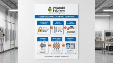
- Follow this sequence: de-energize upstream power, mount the enclosure, connect line-side then load-side conductors, install rated fuses, and confirm with a voltage tester before re-energizing
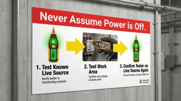
- Apply LOTO (Lockout/Tagout) per OSHA 1910.147 before starting — never assume power is off without confirming with a non-contact voltage tester
- Match fuse amperage to the load's full-load current; NEC 430.52 allows time-delay fuses sized up to 175% of motor FLA for startup inrush
- Wire gauge must match breaker and load ratings; torque all terminals to NEC 110.14(D) specs using 600V-rated copper conductors
- After wiring, verify correct phase rotation and confirm no voltage on the load side before closing the disconnect
Wiring a Fused Disconnect Switch
Wiring a fused disconnect switch covers several distinct phases: site preparation, upstream isolation, enclosure mounting, conductor routing and termination on both line and load sides, fuse installation, and validation testing. Each phase carries code requirements and safety obligations. This work demands knowledge of electrical codes, load calculations, and safe work practices — it is not a task for untrained personnel.
Time expectations: A standard single-phase or three-phase wiring job typically takes 2-4 hours for an experienced technician. Allow additional time if conduit runs are involved or if LOTO coordination is required across multiple shifts or departments.
Prerequisites and Safety Requirements
Before touching the disconnect, verify the following site and system readiness checks:
Upstream Circuit Verification:
- Confirm the upstream circuit breaker or main panel is identified, accessible, and can be locked out
- Verify you have the correct circuit — test with a non-contact voltage tester before proceeding
- Ensure the upstream breaker has a LOTO device or can accept a padlock
Enclosure and Equipment Compatibility:
- NEMA rating match: Confirm the enclosure NEMA rating matches the installation environment (NEMA 4X for wet or corrosive areas, NEMA 12 for indoor industrial)
- Amp rating: Per NEC 430.110(A), the disconnect switch amp rating must be at least 115% of the load's full-load current
- Fuse compatibility: Verify fuse type (Class J, Class CC, Class L, etc.) is compatible with the switch's fuse carrier
- Voltage rating: Confirm voltage rating matches the circuit (120V, 240V, 480V, 600V)
LOTO Requirements (Non-Negotiable): Per OSHA CFR 1910.147, all energy sources must be isolated and locked out before wiring begins. The padlockable handle on the disconnect itself is not a substitute for locking out the upstream breaker; both must be addressed. Only "authorized employees" may apply LOTO devices.
Do Not Proceed If:
- The upstream circuit cannot be positively isolated and locked out
- The enclosure's NEMA rating is inadequate for the environment
- The disconnect switch is undersized or incorrectly rated for the load
Tools and Materials Required
Essential Tools:
- Non-contact voltage tester (required before any work begins — no exceptions)
- Clamp meter or multimeter
- Insulated screwdrivers (flathead and Phillips, correct size for bonding lugs)
- Wire strippers
- Conduit knockout punch or drill (if running conduit)
- Torque screwdriver or torque wrench (for proper lug tightening per NEC 110.14(D))
- Permanent marker for labeling
Essential Materials:
- Properly rated fused disconnect switch (UL Listed, correct NEMA enclosure type)
- Fuses matched to load amperage and fuse carrier type
- 600V-rated solid copper wire in the correct gauge (e.g., #10 AWG for 30A, #6 AWG for 60A)
- Grounding conductor (same gauge as circuit conductors)
- Conduit and fittings (if applicable)
- Wire labels or panel labels
⚠ Wire Type Warning: Avoid stranded wire at screw lug terminals. Heat cycling under load causes strands to loosen, creating a high-resistance connection that can arc and damage the terminal. Use solid copper conductors, or install ferrules (crimp-end fittings) if stranded wire is unavoidable.
How to Wire a Fused Disconnect Switch: Step-by-Step
Wiring follows a strict sequence. Skipping steps (especially safety and termination steps) is the most common cause of connection failures, blown fuses on first energization, and arc flash events.
Step 1 — De-energize and Verify
**Shut off the upstream circuit breaker** and apply LOTO hardware (padlock and tag). Use a non-contact voltage tester at the panel and at the disconnect's intended line-side entry point to confirm zero voltage. Never assume power is off — verify using the "live-dead-live" method: test the tester on a known live circuit, test your work area, then test the tester again on a live circuit to confirm it's working.
Step 2 — Mount the Enclosure
Secure the disconnect switch enclosure to the wall, panel, or equipment frame within sight of the load. NEC 430.102(B) requires the disconnect to be visible from the equipment it serves (within 50 feet), or lockable in the open position if not within sight. Ensure the enclosure is level and accessible for handle operation.
Step 3 — Route and Prepare Conductors
Run line-side (supply) conductors and load-side (equipment) conductors through the appropriate knockouts using conduit fittings. Strip wire ends to the length specified by the terminal lug (typically printed inside the enclosure or in the manufacturer's wiring diagram). Maintain separation between line and load wiring inside the enclosure to prevent accidental contact during service.
Step 4 — Terminate Line-Side Conductors
Connect the incoming hot conductor(s) to the LINE terminals (top of the switch, above the fuse carriers). The neutral lug receives the neutral conductor — neutral is not switched and must remain continuous. Route the grounding conductor to the ground/bonding lug.
Tighten all lugs firmly using the correct screwdriver or torque wrench to the manufacturer's specified torque value. Per NEC 110.14(D), torque values must be achieved using calibrated tools. "Hand-tight" is a code violation and a primary cause of arc flash incidents.
Step 5 — Install Fuses and Terminate Load-Side Conductors
Insert the correct fuse(s) into the fuse carriers. Fuse amperage must match the load's full-load current, not simply the switch's maximum rating. For motor circuits, NEC 430.52(C)(1) permits sizing time-delay fuses up to 175% of the motor's full-load amperes (FLA) to handle the 6–8× inrush current at startup.
Once fuse sizing is confirmed, complete the load-side connections:
- Seat fuse carriers fully until they click or lock
- Connect load-side conductors to the LOAD terminals (below the fuse carriers)
- Ground the load-side equipment frame via the grounding conductor
Step 6 — Label and Close
Clearly label the disconnect switch with the circuit it controls, the voltage, and the amperage per NEC 110.22. Install all terminal covers or shrouds for IP/NEMA protection. Close and latch the enclosure. Do not re-energize until post-installation checks are complete.
Post-Wiring Checks and Validation
Skipping validation is dangerous. A visually complete installation can still have reversed line/load connections, incorrect fuse ratings, or a loose lug that will fail under first load — validation catches these before they become arc flash incidents or equipment damage.
Visual Inspection Before Re-energizing
- Confirm all conductors are fully seated in their lugs with no exposed bare copper beyond the terminal
- Verify fuses are the correct type and rating and are fully seated in carriers
- Check that the enclosure is fully closed and all knockouts not in use are sealed
- Confirm the handle moves freely between ON and OFF positions
Continuity and Isolation Check
With the handle in the OFF position, use a multimeter to confirm there is no continuity between line-side and load-side terminals on each pole. This confirms the switch breaks the circuit when open.
Live Voltage Verification After Re-energization
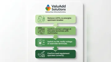
- Remove LOTO and re-energize the upstream breaker
- With the disconnect in the OFF position, confirm correct voltage at the line-side terminals using a multimeter
- Switch to ON and verify the same voltage appears at the load-side terminals
- Confirm the load equipment operates correctly
Common Wiring Problems and How to Fix Them
Fuses Blow Immediately on First Energization
Fuses blow the moment the disconnect is switched ON during initial commissioning.
Likely causes:
- Fuses undersized relative to the load's inrush or locked-rotor current (motors draw 6–8× FLA on startup)
- Wiring error creating a short circuit in load-side conductors or within the connected equipment
Fix:
- Verify the load's full-load current and locked-rotor/inrush current rating
- Confirm whether time-delay fuses are required for motor loads
- Inspect load-side conductors for insulation damage or unintended contact before replacing fuses
Overheating at Lug Terminals
Terminals or fuse carriers show discoloration, melting, or burning smell after operation.
Likely causes:
- Loose lug connection (the most common wiring error)
- Stranded wire used where solid copper is specified
- Wire undersized for the load current
Fix:
- De-energize and apply LOTO before touching any terminals
- Re-terminate the affected conductor to the manufacturer's torque specification
- Replace damaged fuse carriers or terminals
- Confirm wire gauge matches load requirements
Disconnect Handle Won't Lock in the OFF Position
The padlockable handle does not stay locked in the open (OFF) position, or the interlock mechanism fails to engage.
Likely causes:
- Enclosure cover not fully closed
- Handle or interlock bracket installed incorrectly during mounting
- Shaft length mismatch when an extension shaft is used
Fix:
- Verify the enclosure door is fully latched before engaging the handle lock
- Review the manufacturer's handle installation instructions for interlock alignment
- Confirm the shaft and handle model are compatible with the disconnect switch
Pro Tips for Wiring a Fused Disconnect Switch Effectively
A few field-tested practices can prevent callbacks, failed inspections, and safety hazards down the line.
- Use time-delay (dual-element) fuses for motor loads — standard fast-acting fuses will blow on startup inrush even when correctly sized, while dual-element fuses absorb the surge without sacrificing short-circuit protection
- Use aluminum wire only on CU-AL rated disconnects, with the terminal confirmed for aluminum service and anti-oxidant compound applied before terminating — aluminum at standard screw terminals is a fire risk
- Photograph the completed wiring, record fuse types and ratings on the inside of the enclosure door, and log the disconnect in the facility's panel directory before closing up — this is required for many inspections and speeds up future maintenance
Conclusion
Wiring quality determines whether a fused disconnect switch actually protects equipment and personnel — or becomes the failure point it was meant to prevent. A correctly wired switch with properly rated fuses is the last line of defense against short circuits and overloads in industrial systems.
Skipping any step in the process — planning, LOTO compliance, correct termination, post-installation validation — creates real risk. Follow the full sequence every time, verify continuity and polarity before re-energization, and document the completed installation for future maintenance. In industrial environments, that record isn't just good practice; it's what keeps the next technician safe.
Frequently Asked Questions
How does a fused disconnect switch work?
A fused disconnect switch combines a mechanical isolation switch with integrated fuse protection. The handle mechanically breaks the circuit (disconnecting load from supply), while the fuses interrupt the circuit automatically if overcurrent or short-circuit conditions exceed the fuse rating.
Will a fused disconnect work without fuses?
While the handle mechanism can still physically open and close without fuses installed, operating without fuses eliminates all overcurrent protection. The switch effectively becomes a non-fused disconnect, leaving the circuit and equipment unprotected against short circuits and overloads.
What size fuse should I use for a fused disconnect switch?
Fuse amperage must match the load's full-load current. For motor circuits, NEC Article 430.52 permits sizing time-delay fuses up to 175% of FLA (and up to 225% under exceptions). Always verify the fuse class (such as Class J or Class RK5) matches the application's fault current requirements.
What wire gauge do I use for a fused disconnect switch?
Wire gauge must match both the disconnect's ampere rating and the upstream overcurrent device — for example, 30A circuits typically use #10 AWG and 60A circuits use #6 AWG. Always use 600V-rated copper conductors and confirm sizing against NEC Table 310.16 for your specific installation.
Does a fused disconnect switch need to be within sight of the equipment?
Per NEC Article 430.102, the disconnect must be within sight of the motor or equipment it serves (within 50 feet and visible), or it must be capable of being locked in the open (OFF) position if located out of sight.
What is the difference between a fused and a non-fused disconnect switch?
A fused disconnect provides both isolation and integrated overcurrent/short-circuit protection via fuses, while a non-fused disconnect provides only isolation, relying on an upstream circuit breaker for overcurrent protection. Fused disconnects are preferred for protecting high-value equipment like motors and industrial machinery.