Have you ever seen production come to a sudden stop because a control panel failed? In many facilities, that single moment can cost thousands or even hundreds of thousands of dollars per hour. Many manufacturers report unplanned downtime losses averaging around US $260,000 per hour.
Industrial control panels are the backbone of modern operations, powering processes, protecting equipment, and keeping production running safely and efficiently. Because so much depends on them, understanding how panels are designed, wired, protected, and maintained is not optional; it’s essential for engineers, technicians, and maintenance teams.
This guide gives you the foundational knowledge you need to design, troubleshoot, and maintain electrical control panels with confidence, helping you improve safety, maximize uptime, and support more reliable plant operations.
Key Highlights
Industrial control panels are mission-critical, and failures can cost over $260,000/hour in downtime, making reliability non-negotiable.
They handle power, automation, protection, and safety, acting as the “brain” that keeps motors, drives, and processes running smoothly.
Knowing panel architecture, power distribution, motor control, PLC logic, wiring, and enclosure design is essential for design, troubleshooting, and maintenance.
Power, control, and safety circuits each have a distinct role, ensuring proper energy flow, interlocking, E-stops, grounding, and fail-safe behaviour.
Right components + good maintenance = reliability, and partners like ValueAdd help teams choose compliant, durable control panel parts that prevent failures and reduce downtime.
What Is an Industrial Electrical Control Panel?
An industrial electrical control panel is a centralized system that houses electrical and automation components responsible for managing power distribution, controlling equipment operation, and ensuring safe, reliable process performance. It coordinates how machinery behaves, responds to inputs, and protects itself under abnormal conditions.
Think of the control panel as both the brain (decision-making logic) and the circulation system (power distribution) for industrial equipment.
Why Control Panels Are Critical?
Control panels are essential because they:
Ensure safe and stable power delivery to motors, drives, and equipment
Execute automation logic that controls sequences, timing, and process flow
Provide built-in equipment protection, preventing damage and downtime from overloads, electrical faults, or power disturbances
Enable monitoring and diagnostics, helping teams identify problems before failure
Support operator control and visibility, enabling safe interaction with complex machinery
Where Control Panels Are Used?
Control panels are found across nearly every industrial and infrastructure environment, including:
Manufacturing and process production lines
OEM machinery and packaged equipment systems
Municipal water and wastewater treatment facilities
Utility and electrical distribution equipment
Commercial and institutional facility systems
Data-critical and automation-dependent environments
Anywhere equipment must run continuously, safely, and intelligently, there’s a control panel making it happen.
Purpose & Core Functions of Control Panels
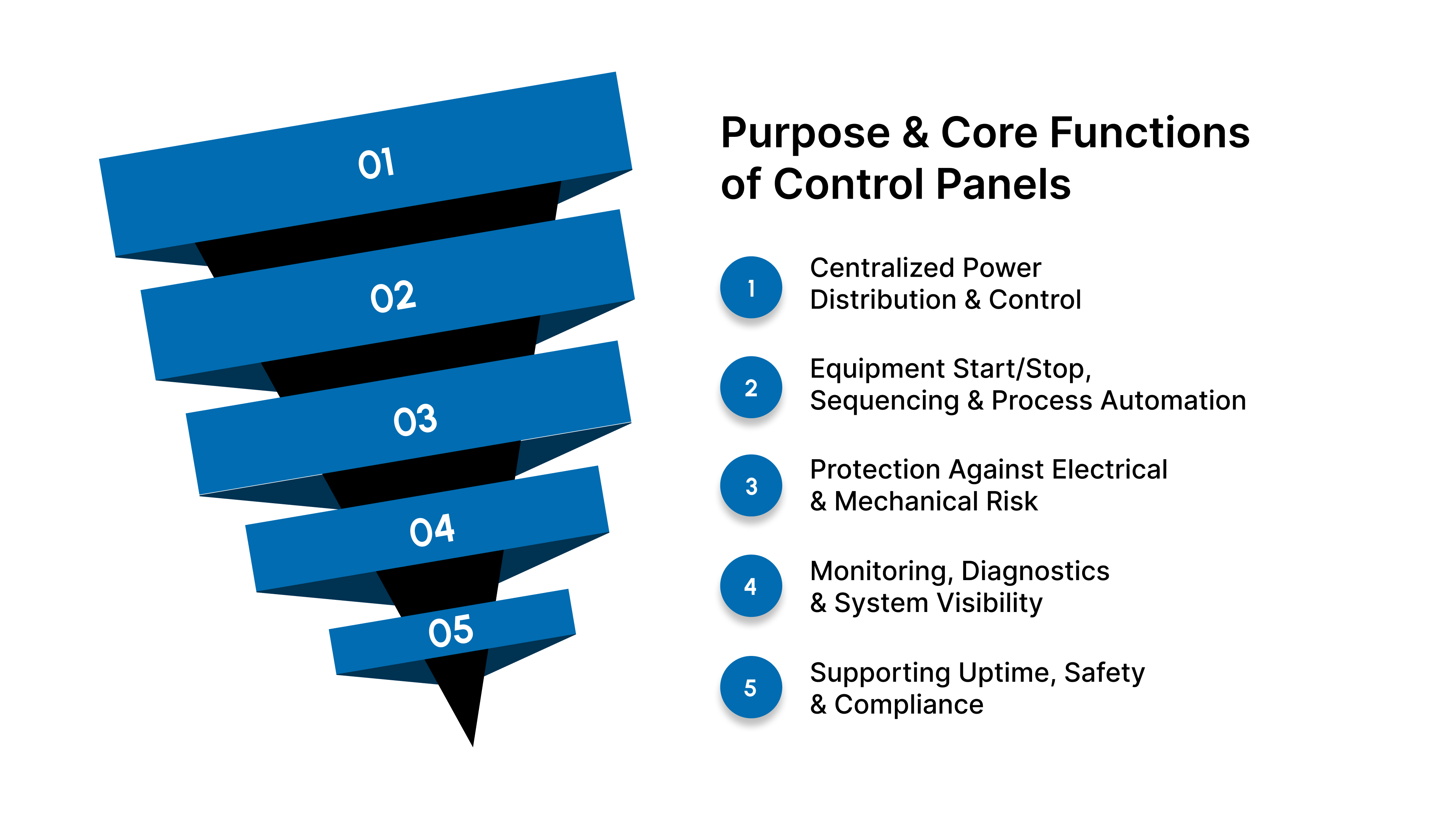
Industrial electrical control panels exist to manage power, control equipment behavior, protect assets, and ensure safe, continuous operation. Their design and performance directly influence the efficiency, reliability, and safety of industrial processes.
1. Centralized Power Distribution & Control
A control panel serves as the unified point where electrical power enters, is conditioned, and is distributed to equipment and subsystems. It routes power safely and efficiently to motors, drives, instrumentation, and auxiliary components while controlling how and when each device operates.
2. Equipment Start/Stop, Sequencing & Process Automation
Control panels govern how equipment behaves during operation:
Starting and stopping machinery
Coordinating timing and sequencing between systems
Executing automated routines and process logic
This automation capability enables repeatable, precise, and efficient operation, essential for production quality and throughput.
3. Protection Against Electrical & Mechanical Risk
Control panels incorporate protective components that safeguard both equipment and personnel from:
Overloads
Short circuits and arc-fault events
Harmonics and electrical noise related to motor drive systems
Voltage disturbances and power instability
Effective protection prevents damage, minimizes downtime, and extends equipment life.
4. Monitoring, Diagnostics & System Visibility
Modern panels provide real-time insight into system status and performance. Indicators, meters, PLC/HMI data, and monitoring relays make it possible to detect abnormal conditions early and troubleshoot faults quickly, reducing reliance on guesswork.
5. Supporting Uptime, Safety & Compliance
Control panels play a central role in maintaining system health and meeting safety expectations:
Reducing incidents caused by electrical failures
Supporting lockout/tagout, E-stop, and safe-shutdown functions
Enabling compliance with industry and electrical standards
Reliable control panel design and knowledge directly improve equipment availability, worker safety, and operational continuity.
Internal Architecture of a Control Panel
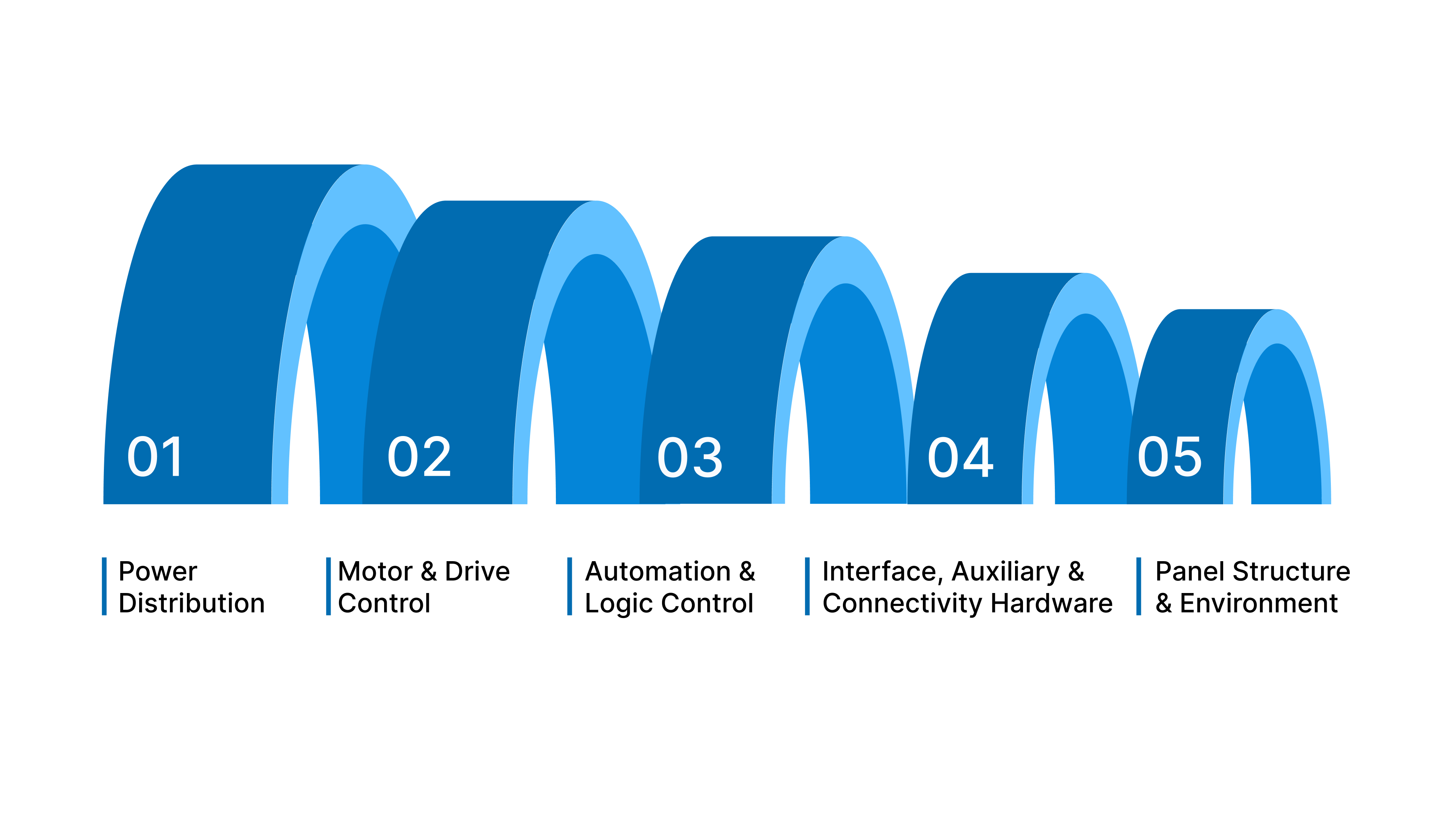
A control panel is a structured ecosystem of electrical and automation components working together to power, protect, and control industrial equipment. Each section inside the panel has a specific function and must be designed, installed, and maintained with precision to ensure reliability and safety.
A. Power Distribution
This is the entry point and backbone of the electrical system, where incoming facility power is managed and routed throughout the panel.
Incoming power entry — connection point from facility mains or transformer
Main disconnect / load-break switch — isolates power for service and emergency shutdown
Circuit breakers/fuses/branch protection — prevent overloads, faults, and short circuits
Transformers/power supplies — step down and convert power to usable control voltages (e.g., 480V → 120V/24V)
Effective power distribution ensures stable electrical performance and protects downstream equipment.
B. Motor & Drive Control
These components manage the starting, stopping, speed control, and protection of rotating equipment such as pumps, conveyors, compressors, and mixers.
Contactors, overload relays — enable motor control and protect from thermal overload
Soft starters / VFD-related peripherals — improve motor performance, reduce mechanical stress, and control acceleration
Monitoring relays & protection functions — detect imbalance, phase loss, voltage issues, or motor faults
Strong motor control architecture reduces failures and extends equipment life.
C. Automation & Logic Control
This layer forms the decision-making brain of the system, executing commands, processing logic, sequencing, and communication.
PLCs & I/O modules — collect inputs, process logic, and generate outputs
HMIs & operator interfaces — provide real-time visibility and control for operators and technicians
Communication networks & internal switching — enable data exchange between devices and higher-level systems
Reliable automation platforms are the key to efficiency, repeatability, and modern plant optimization.
D. Interface, Auxiliary & Connectivity Hardware
These elements support safe, clear interaction between people, machines, and wiring infrastructure.
Pushbuttons, selector switches, pilot lights — operator control and status indication
Terminal blocks, wiring accessories, DIN rails — organize connections and maintain structured routing
Internal labeling & cable management — ensure clarity, traceability, and streamlined maintenance
Clean layout and labeling dramatically improve troubleshooting speed and safety.
E. Panel Structure & Environment
The physical enclosure and environmental controls protect components from heat, dust, moisture, vibration, and external contamination.
Enclosure construction & material choices — steel or polycarbonate, depending on application, environment, and durability needs
Climate control, airflow & thermal management — cooling, ventilation, and heat dissipation solutions to prevent performance degradation or failure
Proper enclosure and environmental design support long system life and consistent reliability.
Understanding Panel Circuits
Control panels contain multiple types of electrical circuits that work together to safely operate equipment, manage automation logic, and protect personnel and assets. Understanding how these circuits function is critical for troubleshooting, system design, and safe maintenance.
1 Power Circuits
Power circuits distribute electrical energy to the loads (motors, heaters, drives, transformers, etc.) and form the backbone of the control panel.
Incoming power → main disconnect → branch distribution
Power enters the panel from the facility supply and is routed through a main disconnect or load-break switch for isolation and safe service. From there, power is distributed through breakers or fuses to downstream equipment.Voltage levels
Industrial systems commonly operate on higher voltages (480V, 600V, 240V, etc.) for motors and lower control voltages (120V, 24V AC/DC) for electronics.Short-circuit ratings & breaker sizing
Protection devices must be properly rated for:Available fault current
Load requirements
Trip curves suited for motor or general loads
Correct sizing prevents nuisance tripping, overheating, or catastrophic component failure.
2 Control Circuits
Control circuits manage signals and decision-making rather than delivering raw power. They allow equipment to operate in a controlled and coordinated manner.
Low-voltage signaling logic: Typically 24VDC or 120VAC, used for inputs, outputs, pushbuttons, pilot devices, and relay coils.
Relays & interlocking logic: Relays convert low-voltage signals into control actions; interlocks prevent unsafe or conflicting operations.
Safety feedback: Used to verify conditions such as guard closed, pressure safe, temperature normal, phase correct, etc.
Control circuits translate automation logic into equipment action.
3 Safety Circuits
Safety circuits exist to protect people and equipment, and they must operate independently and reliably under worst-case conditions.
Emergency-stop (E-stop) loops
Designed to remove power immediately from hazardous motion or processes.Redundancy & monitored safety relays
Ensures faults are detected, and failures default to a safe condition.Lockout/Tagout (LOTO)
Prevents accidental startup during service and maintenance.Fail-safe design philosophy
Systems must shut down safely when wiring is broken, contacts fail, or power is lost, not continue running.
Safety circuits take priority over all other logic and must be tested regularly.
4 Panel Grounding & Bonding
Grounding ensures electrical stability and safety, while bonding provides a low-impedance path for fault current, preventing shock hazards and electrical noise problems.
Key principles:
Equipment grounding
Protects personnel by ensuring all metal enclosures and equipment are tied to earth ground.Signal grounding
Used to stabilize low-voltage electronics and reduce interference.EMI/RFI noise reduction
Proper grounding, shielding, and cable routing improve automation performance and prevent unreliable behavior from drives or high-frequency devices.Reliability impact
Many intermittent faults trace back to poor grounding, loose bonding straps, or improper shield termination.
Good grounding practices equal cleaner signals, fewer failures, and easier troubleshooting.
How to Read Electrical Schematics
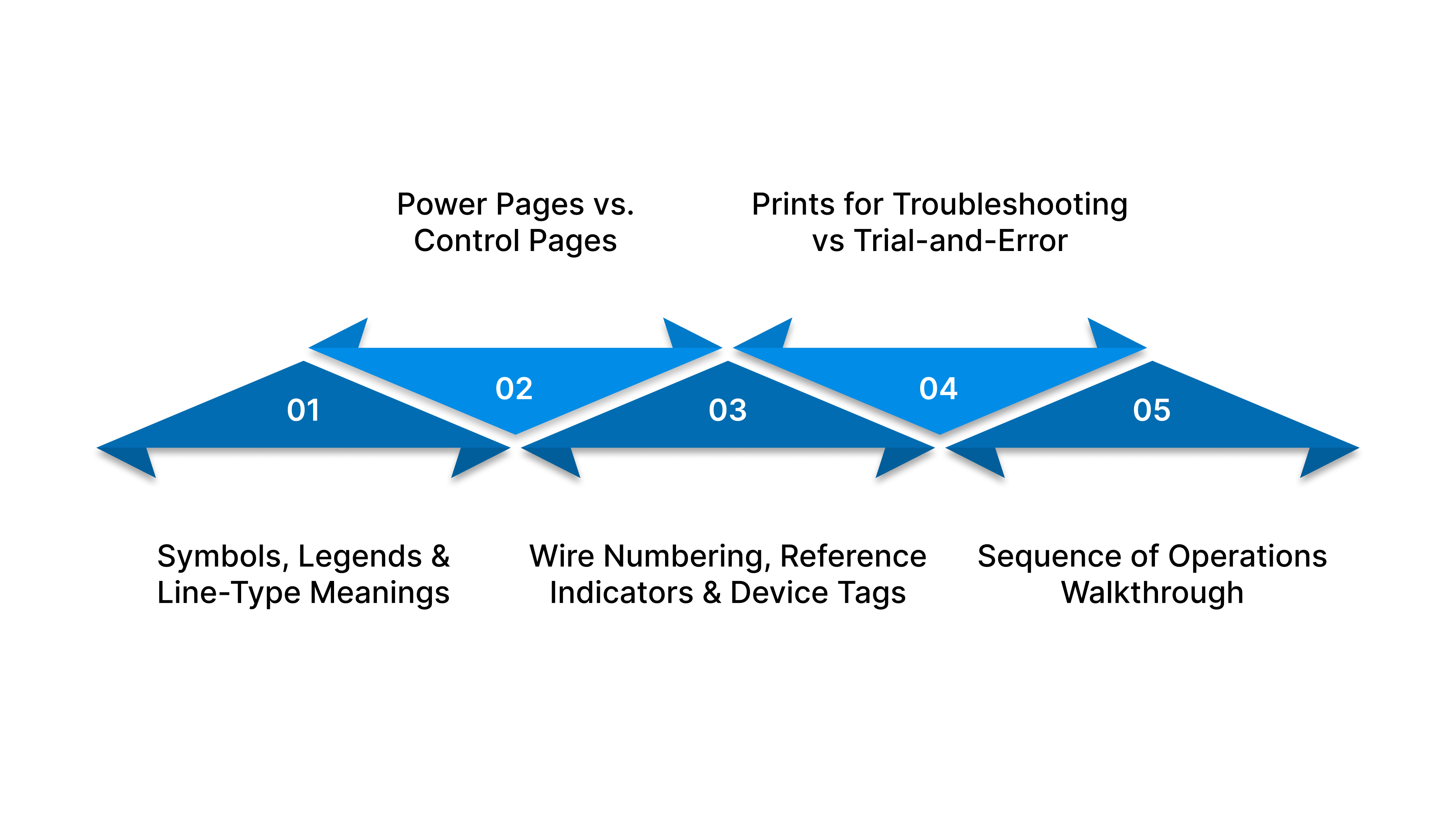
Being able to read electrical schematics is one of the most important skills for anyone working with control panels. Schematics provide a roadmap of how a system is designed to operate, showing how power flows, how signals move, and how components interact. Strong schematic literacy dramatically increases troubleshooting speed, accuracy, and confidence.
1. Symbols, Legends & Line-Type Meanings
Schematics use standardized electrical symbols to represent components and circuit functions. The legend or symbol key included in drawings explains how each component is represented.
Symbols identify devices such as relays, switches, breakers, motors, and sensors.
Line types indicate the function of wiring: power, control, safety, communication, or field wiring.
Dashed lines often represent logical grouping or enclosure boundaries.
Learning the symbol standard used in your facility (ANSI, IEC, or NFPA 79) is essential for accurate interpretation.
2 Power Pages vs. Control Pages
Most industrial schematics are divided into two major sections:
Power pages — Show incoming power, distribution, breakers, transformers, motor feeders, and grounding. These indicate how power flows through the system.
Control pages — Show logic circuits, pushbuttons, relays, PLC I/O, sensors, safety circuits, and automation behavior.
Understanding which section you’re viewing prevents confusion and speeds troubleshooting.
3 Wire Numbering, Reference Indicators & Device Tags
Schematics use structured naming systems to identify and track every wire and device in the panel:
Wire numbering — Each wire has a unique ID to trace its path through terminal blocks and field connections.
Device tags (e.g., K1 for relay, M1 for motor, Q1 for breaker), identify components throughout pages.
Reference indicators — Show where a circuit continues on another page (e.g., “See Page 12, Line B4”).
Using these identifiers keeps navigation organized and reduces guesswork.
4 Using Prints for Troubleshooting vs Trial-and-Error
The most skilled technicians don't guess; they trace logic using schematics.
Start at the device that isn't functioning.
Trace backward along the schematic to find where the signal or power path stops.
Check relays, contacts, and terminal points systematically.
Confirm conditions rather than replacing parts blindly.
This method can reduce downtime dramatically and prevent unnecessary replacements.
5 Sequence of Operations Walkthrough
A Sequence of Operations (SOO) describes how equipment is intended to behave step-by-step under normal and abnormal conditions.
Example steps in a sequence may include:
Power applied, system initializes
Safety circuit verified
Start command received
Motor or process begins operation
Feedback confirms correct status
The system continues or shuts down based on conditions
Understanding SOO helps:
Diagnose where a process is failing
Validate logic changes
Train operators and new technicians
Reading schematics together with the SOO gives a complete understanding of how the machine is supposed to function.
How ValuAdd Supports Reliable Control Panel Design & Performance
Building reliable industrial control panels requires more than assembly and wiring; it depends on selecting the right components, applying them correctly, and integrating products that work cohesively.
Engineering-driven product selection support to ensure the correct components are specified for power distribution, control logic, protection, and automation needs.
Comprehensive product portfolio including industrial enclosures, climate control, circuit breakers, disconnect switches, relays, monitoring relays, pilot devices, power-quality equipment, and industrial UPS solutions, all designed to work cohesively inside control panels.
Standardization assistance that simplifies BOMs, improves panel repeatability, reduces component variation, and speeds maintenance and troubleshooting.
Hands-on application support for solving real-world challenges such as thermal issues, harmonics, short-circuit compliance, signal noise, and retrofit upgrades.
Training and knowledge transfer for panel shops, OEMs, distributors, and maintenance teams, improving installation quality and reducing field-based trial-and-error.
Reliability and uptime optimization through guidance on correct breaker sizing, filtering solutions, grounding, ventilation, and sustainable panel design.
Collaborative partnership model, operating as an extension of engineering and support teams rather than a transactional product provider.
ValuAdd supports engineering and maintenance teams with technical expertise and a complete portfolio of industrial electrical solutions that improve uptime, performance, and long-term maintainability.
Best Practices for Long-Term Reliability
Preventing downtime and improving system reliability comes from consistent, disciplined practices, not just fixing problems after they happen. Implementing the following habits will strengthen equipment performance, simplify troubleshooting, and extend the life of control panel assets.
Standardize components to reduce maintenance complexity: Using consistent manufacturers and part families improves compatibility, simplifies training, and streamlines spare-parts inventory.
Document changes immediately and store updated drawings in the panel: Accurate schematics and revision history enable faster troubleshooting and prevent costly mistakes.
Use torque tools according to manufacturer specifications: Ensures optimal electrical contact integrity, prevents overheating, and eliminates loose-connection failures.
Perform scheduled thermal inspections and electrical audits: Infrared scanning and preventative reviews help identify problems early, before they lead to unplanned downtime.
Conclusion
Control panels are the foundation of modern industrial reliability. Understanding how they are built, how they operate, and how to troubleshoot them effectively is essential for maintaining safe, efficient, and productive operations.
By applying structured troubleshooting, proper documentation, solid design practices, and proactive maintenance, engineering and maintenance teams can significantly reduce downtime, extend equipment life, and increase system stability.
Strong control panel performance is never accidental; it is the result of informed decisions, quality components, and knowledgeable support. Ready to improve control panel reliability and make smarter component decisions?
Contact ValuAdd today for engineering support, product guidance, and practical solutions that strengthen your electrical systems and reduce downtime.
Frequently Asked Questions (FAQ)
1. Why is documentation so critical to panel maintenance?
Accurate drawings and revision records reduce troubleshooting time, avoid wiring mistakes, and support safe operation.
2. What are the most important components inside a control panel?
Key components include breakers, disconnects, transformers, relays, PLCs, HMIs, power supplies, wiring, terminal blocks, and the enclosure that houses them.
3. Why do control panels fail most often?
Common causes include loose wiring, overheating, incorrect component sizing, grounding issues, and poorly documented modifications.
4. What is the difference between power circuits and control circuits?
Power circuits deliver energy to equipment (motors, drives, heaters), while control circuits manage low-voltage signals that direct how and when equipment operates.
5. Why is grounding so important in control panels?
Proper grounding prevents electrical noise, stabilizes signals, protects personnel, and reduces unpredictable shutdowns or equipment damage.