Introduction
A plant running 30 motors across distributed starters doesn't have a motor problem — it has a control problem. Scattered disconnects, inconsistent protection settings, and no central fault visibility turn routine troubleshooting into a time sink that costs real production hours.
For plant engineers and system integrators, this translates directly to downtime risk and maintenance overhead. Manual coordination of protection settings introduces human error, and keeping dozens of independent starters operational drains both budget and staff time.
The Motor Control Center (MCC) solves these problems by consolidating motor control into one centralized system. This guide covers what an MCC is and its core components, how MCC buckets function, and how to recognize when an upgrade is overdue.
What Is a Motor Control Center (MCC)?
The National Electrical Code (NEC) Article 100 defines a Motor Control Center as "an assembly of one or more enclosed sections having a common power bus and principally containing motor control units" [7]. This centralized architecture distinguishes MCCs from standalone motor starters or distributed panel setups. All circuits share a common power backbone rather than operating as isolated units.
Where MCCs Are Installed
MCCs are typically installed in dedicated control rooms or air-conditioned enclosures to protect sensitive components from environmental stress. Industries that depend most heavily on MCCs include:
- Manufacturing plants (food processing, automotive, textiles)
- Water and wastewater treatment facilities
- Oil and gas processing plants
- Mining operations
- Power generation facilities
The global MCC market reached $6.57 billion in 2025, with industrial applications accounting for 71.9% of revenue in 2023 [12] [13]. That concentration in industrial use points directly to the operational problems MCCs were built to solve.
Problems MCCs Solve
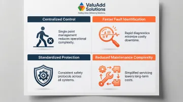
MCCs address four major operational pain points:
- Eliminates the need to walk between multiple locations to start, stop, or troubleshoot motors
- Centralizes monitoring so technicians can identify a failed motor circuit faster
- Standardizes overload protection and control logic across all motor circuits
- Consolidates independent starters into modular, serviceable units — reducing maintenance complexity
Key Components Inside an MCC
While MCCs vary in size and configuration, they share a common internal architecture built around a bus system, modular control units, and integrated monitoring.
The Bus System: Horizontal and Vertical Buses
The horizontal bus runs the length of the MCC enclosure, connecting the incoming main power supply across all vertical sections. It serves as the primary power distribution backbone, with standard ratings from 600 A to 3,200 A using copper (tin- or silver-plated) or aluminum (tin-plated) bars built to withstand mechanical stress during faults.
The vertical bus branches from the horizontal bus into each vertical section, distributing power to individual starter units (buckets or drawers). Its rating must account for the collective load of all motors it serves, with standard options at 300 A, 600 A, 800 A, and 1,200 A.
Table: Typical MCC Bus Ratings
| Component | Standard Ratings | Common Materials | Function |
|---|---|---|---|
| Horizontal Bus | 600 A to 3,200 A | Copper/Aluminum (tin-plated) | Distributes main power across sections |
| Vertical Bus | 300 A to 1,200 A | Copper (tin-plated) | Feeds individual buckets |
Motor Control Units
Motor control units are the functional heart of the MCC. Each unit contains the switching, protection, and control elements for one motor circuit. These units are modular—designed as buckets or drawers—and can be individually serviced without taking down the entire panel. That capability becomes especially valuable once you factor in the control and monitoring layer built into each unit.
Control and Monitoring Features
Modern MCCs go beyond simple switching. Integrated PLCs, VFDs, and soft starters enable precise motor control, while Ethernet and fieldbus connectivity support remote monitoring, diagnostics, and data logging—giving maintenance teams the visibility needed for predictive maintenance.
Protective functions built into the control layer include:
- Overload detection and automatic motor shutdown
- Phase loss protection to prevent single-phasing damage
- Fault logging for root cause analysis
- Ground fault detection
When functioning correctly, these features reduce unplanned downtime by catching problems before they escalate into catastrophic failures.
What Is an MCC Bucket?
An MCC bucket is the modular plug-in unit that houses all protection and control elements for a single motor circuit. Each bucket is self-contained: it includes a motor starter, overload relay, disconnect or circuit breaker, and control circuitry—and is designed to slide into or bolt onto the MCC structure independently.
Parts of an MCC Bucket
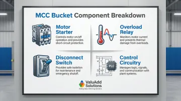
Each bucket contains four core components:
- Motor starter — A DOL contactor, soft starter, or VFD that determines how the motor is started and controlled. The choice depends on load type and starting requirements.
- Overload relay — Thermal or electronic relays sized to the motor's full-load amperage. They trip the circuit if sustained overcurrent is detected, protecting the motor from heat damage.
- Disconnect switch or circuit breaker — Isolates the bucket from the power bus for safe maintenance or emergency shutdown, without affecting adjacent buckets.
- Control circuitry — Internal wiring, push buttons, pilot lights, and contactors that enable manual or automated operation. PLC and SCADA signals interface here.
MCC Bucket vs. MCC Drawer: What's the Difference?
The terms are sometimes used interchangeably, but they refer to distinct formats with different standards behind them:
| Bucket | Drawer | |
|---|---|---|
| Shape | Cube or square | Horizontal sliding unit |
| Standard | ANSI/NEMA | IEC 61439 |
| Common Region | North America | Europe and international |
Project location and specification requirements determine which standard applies. Both formats are modular, but not all units slide out freely. Some buckets are fixed and require hardwired disconnection before removal; drawers can also be fixed-style in certain configurations.
Types of Motor Starters Used in MCC Buckets
The type of motor starter installed in a bucket is one of the most consequential design decisions—it determines starting current, mechanical stress on driven equipment, energy efficiency, and controllability.
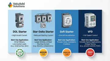
Direct-On-Line (DOL) Starter
The simplest and lowest-cost option. DOL connects the motor directly to full voltage at startup. While reliable, it produces high inrush current—typically 4 to 8 times full-load current—and significant mechanical shock. This makes it suitable only for smaller motors or applications where high starting current and torque surges are acceptable.
Star-Delta Starter
Reduces startup voltage by starting the motor in star configuration and switching to delta once it reaches speed. This reduces inrush current to approximately 33% of DOL levels. However, it requires six motor terminals and is unsuitable for motors where voltage must be applied continuously during the transition period. Starting torque is also reduced proportionally, limiting use in high-inertia applications.
Soft Starter
Uses thyristors to gradually ramp up voltage and current during startup, eliminating mechanical shock and reducing electrical stress on both the motor and the MCC. Soft starters are especially valuable in pumps, compressors, and conveyors where sudden torque surges can damage couplings and connected equipment.
ValuAdd's CFMVRMX and MVE-P Series soft starters carry Class E2 load break compliance and integrated programmable control for motor protection in critical industrial applications.
Variable Frequency Drive (VFD)
VFDs control both starting current and ongoing motor speed by varying the frequency of the supplied power. Unlike soft starters, they offer continuous speed control and the greatest energy savings during partial-load operation. According to the U.S. Department of Energy, a VFD driving an exhaust fan at half speed can reduce input power requirements by 82.9% compared to full-speed operation.
VFDs do come at higher cost and introduce harmonic distortion into the electrical system. ValuAdd's IEEE 519-compliant VFDs use H-Bridge multi-level technology to deliver less than 8% total harmonic distortion, protecting sensitive downstream equipment while enabling precise speed control.
Common Causes of MCC Failure
Electrical Overload and Component Aging
Overload relays can fail to detect current anomalies—especially if undersized or worn—leading to overheating, insulation degradation, and contactor failure over time. Research shows that for every 10°C rise in operating temperature above the rated limit, winding insulation life is cut in half [2].
Aging equipment accumulates thermal stress, mechanical wear, and corrosion — all of which accelerate breakdown timelines. Equipment flagged as "at risk" due to age and maintenance history is 10 times more likely to break down, with breakdowns being five times more severe [1].
Nearly 44% of electrical equipment failures are directly linked to poor or non-existent maintenance [1]. Neglected equipment doesn't just fail more often — it fails harder.
Environmental Exposure and Loose Connections
Humidity, dust, and temperature are the top three environmental contributors to electrical failure [1]. Dust accumulation impedes heat dissipation and absorbs moisture, creating conductive paths that lead to tracking and arcing. Corrosive atmospheres degrade insulation and accelerate component wear.
Faulty installation practices compound these issues:
- Bad terminations create resistance hot spots
- Insufficient grounding increases fault risk
- Ignored torque specifications lead to loose connections that overheat
NEMA enclosure ratings (Type 12 for dust, Type 3R for outdoor) are critical for defending against environmental stress [6].
Mechanical Failures Cascading Into Electrical Damage
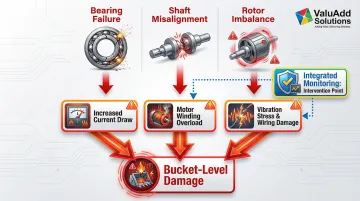
Common mechanical fault sources include:
- Bearing failures that drive up current draw
- Shaft misalignment increasing load on motor windings
- Rotor imbalance creating sustained vibration stress
Each of these stresses the bucket's overload protection and internal wiring. Left undetected, they escalate into bucket-level damage — and at that point, replacement is typically cheaper than repair. Integrated monitoring that tracks vibration, temperature, and current gives maintenance teams the window to intervene before a mechanical problem becomes an electrical one.
When Should You Upgrade Your MCC?
Age and Obsolescence Indicators
MCCs older than 20-25 years often face parts obsolescence, making bucket replacement difficult or impossible [1]. Outdated units may also:
- Lack arc flash mitigation features required by NFPA 70E and IEEE 1584 [3]
- Fail to meet current NEC or NEMA requirements
- Lack communication ports needed to integrate with modern PLC and SCADA systems
Legacy MCCs typically miss critical safety mechanisms like automatic shutters for vertical bus isolation or arc-flash relays. Upgrading with modern trip units or zone-selective interlocking can significantly reduce incident energy levels, improving personnel safety and regulatory compliance.
Capacity and Load Growth
If a facility has expanded its motor count or increased motor horsepower ratings beyond the original MCC design capacity, the horizontal and vertical bus ratings may be undersized for the new load.
Warning signs include:
- Frequent tripping
- Overheating enclosures
- Inability to add new buckets without overloading the bus
When these symptoms appear, a full bus capacity analysis is required to determine if a retrofit or replacement is necessary.
Upgrade to Smarter Motor Control
Once capacity constraints are ruled out, operational priorities like energy efficiency, remote diagnostics, and process control precision become the deciding factor. Upgrading bucket-level components delivers measurable ROI without full MCC replacement. Replacing DOL starters with soft starters or VFDs can:
- Reduce energy consumption by up to 83% in variable-torque applications [4]
- Eliminate mechanical shock and extend equipment life
- Enable remote monitoring and predictive maintenance
ValuAdd's portfolio of VFDs and soft starters (including the Benshaw MVH2 Series VFDs and MVDH Series soft starters) offers a practical upgrade path for facilities improving motor control within an existing MCC structure. These units feature compact footprints sized for MCC bays, with network connectivity options (Modbus RTU, Ethernet IP, Profibus-DP) for direct integration with PLCs and SCADA systems.
Frequently Asked Questions
What is the difference between an MCC and a switchboard?
A switchboard distributes power to various loads (lighting, panels, feeders) while an MCC is specifically designed for motor control—housing starters, overloads, and protection devices for individual motor circuits in a modular, centralized structure.
What is the difference between an MCC bucket and an MCC drawer?
Buckets are cube-shaped and ANSI-compliant for North American installations, while drawers are horizontal sliding units that follow IEC standards common in international projects. Standards compliance—not physical shape—is what separates the two formats.
How long does a motor control center typically last?
MCCs are generally designed for a service life of 20-30 years under proper maintenance conditions. However, component aging, environmental exposure, and load changes can shorten this. Parts obsolescence often becomes the practical end-of-life trigger.
Can you add buckets to an existing MCC without replacing the whole unit?
New buckets can often be added if unused slots are available and the bus rating can accommodate the additional load. However, you must verify compatibility with the existing MCC manufacturer's frame and bus standards before proceeding.
What is the difference between a VFD and a soft starter in an MCC context?
A soft starter manages startup and shutdown only (no ongoing speed control), while a VFD continuously controls motor speed throughout operation. VFDs are better for variable-load applications; soft starters are more cost-effective where only startup protection is needed.
What are the NEC requirements for motor control centers?
NEC Article 100 defines MCCs, while Article 430 (Part VIII, Sections 430.92–430.99) covers motor circuit protection requirements, including overcurrent protection for the common bus and marking requirements [8]. Consult the applicable NEC edition and a licensed electrical engineer for project-specific compliance.