Introduction
NEC Article 430 governs the installation, protection, and control of motor circuits—including detailed requirements for disconnecting means that allow safe de-energization during maintenance or emergencies.
For plant engineers, electrical system integrators, and facility managers in manufacturing, water treatment, oil and gas, and processing plants, these disconnect rules directly affect worker safety, LOTO (Lockout/Tagout) compliance, and whether your installation passes inspection.
Motor disconnect failures create serious risks: a 2023 industrial safety analysis found that electrical equipment lacking proper disconnecting means accounted for 23% of workplace electrical injuries. When technicians cannot safely isolate motor circuits, the result is often delayed maintenance, improvised workarounds, or dangerous energized work—all avoidable through proper NEC Article 430 compliance.
What follows covers location requirements, sizing rules, VFD-specific considerations, and the misconceptions that catch even experienced engineers off guard.
Key Takeaways
- NEC 430.101–430.113 (Part IX) governs disconnect types, ratings, location, and operation
- Minimum 115% FLC sizing: Per 430.110, disconnects must be rated at least 115% of motor full-load current (NEC Tables 430.247–430.250)
- Two location requirements: 430.102(A) covers the controller disconnect; 430.102(B) covers the motor (one device can satisfy both under specific conditions)
- "In sight from" means visible and within 50 feet; lockable remote disconnects are only permitted under narrow exceptions
- VFDs add complexity — Standard AC switches can fail catastrophically when interrupting low-frequency VFD output
What Is the Motor Disconnecting Means Under NEC Article 430?
The motor disconnecting means is a device or group of devices used to disconnect the motor, motor controller, and associated circuit conductors from all ungrounded supply conductors—as defined in NEC Article 100 and mandated under Section 430.101. This device is intended for de-energization during maintenance, inspection, and lockout/tagout procedures.
What it is NOT:
- An emergency stop device
- A motor overload protector
- A branch circuit overcurrent device
These are separate components serving different safety functions. The disconnect is the device a technician locks open before working on the motor or driven equipment.
Multiple Related Requirements in Part IX
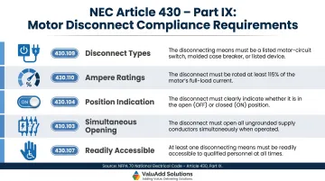
NEC Article 430 Part IX doesn't stop at defining the disconnect — it layers in several distinct compliance requirements, each addressing a specific aspect of safe motor isolation:
| Requirement | Code Section | What It Mandates |
|---|---|---|
| Disconnect types | 430.109 | Limits which devices qualify |
| Ampere ratings | 430.110 | Minimum 115% FLC sizing |
| Position indication | 430.104 | Visible open/closed indication required |
| Simultaneous opening | 430.103 | All ungrounded conductors must open together |
| Readily accessible | 430.107 | At least one disconnect operable without tools or climbing |
These are frequently cited together as "motor disconnect requirements," though each addresses a distinct compliance element.
NEC 430 Location Requirements: Controller Disconnect vs. Motor Disconnect
NEC 430.102 establishes two separate location requirements—one for the motor controller disconnect (430.102(A)) and one for the motor/driven machinery disconnect (430.102(B)). A single physical device can serve both functions if it meets the location criteria for both.
Disconnect for the Motor Controller – NEC 430.102(A)
A disconnecting means must be provided for each motor controller and must be located "in sight from" the controller location. Per NEC Article 100's definition, "in sight from" means the device must be visible and within 50 feet (15 meters).
Exception No. 2: A single disconnecting means is permitted ahead of a group of coordinated motor controllers driving parts of the same machine, provided:
- All controllers are within sight of the disconnect
- All controllers are within sight of the machine
This exception is common in packaging lines, conveyor systems, and automated production equipment where multiple coordinated motors drive a single piece of machinery.
Disconnect for the Motor and Driven Machinery – NEC 430.102(B)
A separate disconnecting means must be installed in sight from the motor and driven machinery location. This is the local disconnect a maintenance technician would use to lock out power before working on the motor or equipment it drives.
The Lockable Remote Exception
The key exception to 430.102(B) allows a lockable remote disconnect (capable of being locked in the open position per NEC 110.25) to substitute for the local motor disconnect under two specific conditions:
- Where placing a disconnect in sight from the motor is impractical or increases hazards
- In industrial facilities with documented safety procedures where only qualified persons service the equipment
The NEC Informational Note identifies scenarios where increased hazards justify the remote disconnect exception:
- Motors rated over 100 hp
- Submersible motors (pumps in wet wells, water intake structures)
- Multi-motor equipment
- Adjustable speed drives (VFDs)
- Motors in hazardous classified locations
Placing a disconnect at a 300 hp motor inside a hazardous enclosure, or at a submersible pump 40 feet underwater, creates greater safety risks than using a properly locked remote disconnect with documented procedures. The remote option is the safer engineering choice in these cases.
One requirement applies in all scenarios: NEC 110.25 mandates that locking provisions remain in place with or without the lock installed. Locking an electrical room door does not satisfy this requirement. The disconnect switch itself must be capable of accepting a padlock.
How to Size a Motor Disconnect Switch Under NEC 430.110
Disconnect sizing rules under NEC 430.110 are specific and distinct from overcurrent protection sizing — and the two are frequently conflated. Getting both right requires separate calculations for separate devices.
Minimum 115% Ampere Rating Rule
Per NEC 430.110(A), the disconnecting means must be rated at no less than 115% of the full-load current (FLC) of the motor(s) it serves. Always round up to the next standard device rating when the calculated value falls between sizes.
FLC values must come from NEC Tables 430.247 through 430.250 — not the motor's nameplate Full Load Amps (FLA). The NEC table values establish code-minimum sizing across all disconnect calculations.
Example: A 25 hp, 460V, 3-phase motor shows 30A on its nameplate. NEC Table 430.250 lists the FLC as 34A. Your disconnect sizing calculation uses 34A × 1.15 = 39.1A minimum. Select a 40A or larger disconnect.
Common Confusion: 115% vs. 125%
The 115% disconnect sizing rule (430.110) and the 125% branch circuit overcurrent protection rule (430.52) apply to different devices — and both calculations are required:
| Device | NEC Section | Multiplier | Purpose |
|---|---|---|---|
| Disconnect Switch | 430.110 | 115% of FLC | Safely isolates motor circuit |
| Branch Circuit OCPD | 430.52 | 125%–250% of FLC* | Protects against short circuits/ground faults |
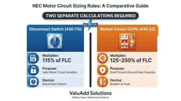
*Depends on breaker type and locked-rotor starting current
One does not replace the other. Both calculations are required for different components in the motor circuit.
Horsepower Rating Requirement
Beyond the ampere rating, the disconnecting means must carry a horsepower rating sufficient for the motor being served. For group motor installations per NEC 430.112, determine the required HP rating as follows:
- Calculate the largest motor's locked-rotor current
- Add the sum of the FLCs of the remaining motors
- Cross-reference the total to NEC Table 430.251 to find the equivalent HP rating
Combined Loads (430.110(C))
When a single disconnect serves a motor plus other loads (lighting, controls, auxiliary equipment), calculate the minimum rating as:
Total FLC = (1.25 × largest motor FLC) + (sum of all other FLCs)
Then cross-reference the resulting locked-rotor current to NEC Table 430.251 to determine the required HP rating of the single disconnect.
Special Considerations: VFDs, Multi-Motor Installations, and Industrial Exceptions
Special Considerations: VFDs and Industrial Disconnect Requirements
Variable Frequency Drive installations introduce significant engineering challenges beyond standard motor circuits.
VFDs Qualify as Motor Controllers
Under NEC Article 100, a VFD qualifies as a motor controller. This means:
- A disconnecting means is required in sight from the VFD (per 430.102(A))
- A separate disconnect may also be required in sight from the motor (per 430.102(B))
The VFD's integral disconnect or upstream lockable disconnect can satisfy 430.102(B) only if the specific exception conditions are met (lockable per 110.25, plus documented procedures or increased-hazard justification).
The VFD Output Switching Hazard
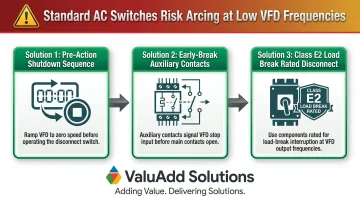
Standard AC disconnect switches are rated for 50/60 Hz interruption. Opening them under load at low VFD output frequencies (e.g., 10 Hz) causes extended arcing because current zero crossings occur far less frequently. At 10 Hz, zero crossings happen every 100 milliseconds — compared to every 8.3 milliseconds at 60 Hz.
The consequences:
- Sustained arcing damages switch contacts
- Arc flash hazard increases significantly
- VFD IGBTs can fail from reflected surge voltages
- Drive may enter fault state and require restart
VFD manufacturers like ABB explicitly warn against opening output contactors while the drive controls the motor. Proper design requires either:
- Pre-action shutdown sequences before disconnect operation
- Early-break auxiliary contacts wired to the VFD's stop input
- Class E2 load break rated disconnect components, engineered for the interrupting demands of VFD output switching where standard AC-rated switches fall short
Selecting components rated for the actual interrupting conditions — not just the nameplate voltage — is essential for both NEC compliance and safe operation.
Readily Accessible Requirement (430.107)
NEC 430.107 requires that at least one of the disconnecting means for the motor circuit must be "readily accessible"—operable without tools (except keys), climbing, or removing obstacles. This is a separate requirement from "in sight from."
Example scenario: A VFD is mounted 8 feet high inside a locked MCC room. The integral disconnect inside the VFD satisfies the "in sight from" controller requirement, but it does NOT satisfy "readily accessible" because it requires a key to access the room and potentially a ladder to reach the device. An additional readily accessible disconnect must be provided elsewhere in the circuit.
Common Misconceptions About NEC Article 430 Motor Disconnects
Misconception #1: Locking the Panelboard Door Satisfies LOTO
Reality: Per NEC 110.25, the disconnect switch itself must be capable of being locked in the open position, with locking provisions that remain in place with or without a lock installed.
Locking a room door, MCC door, or panelboard enclosure does NOT comply. The actual switching mechanism must accept a padlock, hasp, or permanent locking device.
Misconception #2: Motor Disconnect = Emergency Stop
Reality: The motor disconnect under NEC Article 430 is designed for maintenance de-energization (LOTO), not emergency stopping.
| Feature | Motor Disconnect (NEC 430) | Emergency Stop (NFPA 79) |
|---|---|---|
| Purpose | Energy isolation for maintenance | Immediate halt of hazardous motion |
| Response Time | Manual operation, seconds | Milliseconds (control circuit) |
| Circuit Design | Opens power conductors | De-energizes control circuits |
| Reset Requirement | None specified | Must require deliberate restart action |
| Standards | NEC Article 430, NFPA 70E | NFPA 79, ISO 13850 |
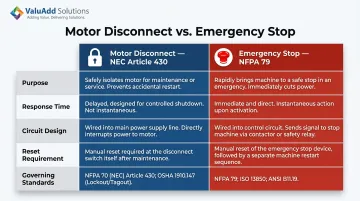
Emergency stops are governed by NFPA 79 and have different response time and circuit architecture requirements. Using a motor disconnect as an E-stop—or vice versa—creates a code gap and a safety risk.
Misconception #3: VFDs Eliminate the Need for Motor Disconnects
Reality: NEC Article 430 contains no explicit exception for VFD-driven motors. The disconnecting means requirement applies regardless of drive technology.
Implementation does require careful attention to VFD output characteristics — particularly when selecting disconnect type and placement. Common considerations include:
- Disconnect location relative to the VFD (line side vs. load side)
- Whether the disconnect must interrupt VFD output or only the supply
- Reflected wave and harmonic effects on disconnect ratings
- Coordination with the VFD's built-in fault protection
Frequently Asked Questions
What are the NEC requirements for motor disconnects?
NEC Article 430 Part IX requires a disconnecting means for both the motor controller (430.102(A)) and the motor/driven machinery (430.102(B)). Each disconnect must be rated at minimum 115% of motor FLC, open all ungrounded conductors simultaneously, visually indicate open/closed position, and meet location requirements relative to the motor and controller.
Which part of Article 430 covers general requirements for motor disconnecting means?
Part IX of NEC Article 430, beginning at Section 430.101, governs all motor disconnecting means requirements. It addresses location, operation, device type, ampere ratings, and group installations — covering everything from accessibility rules (430.107) to approved disconnect types (430.109).
How far should a disconnect be from a motor?
NEC Article 100 defines "in sight from" as visible and no more than 50 feet (15 meters) away. NEC 430.102(B) requires the motor disconnect to be within those bounds unless the lockable remote disconnect exception applies.
Does NEC require exterior disconnect?
NEC Article 430 does not specifically require an exterior disconnect for motors. The requirement is that the disconnect be "in sight from" the motor and driven machinery (or meet the lockable remote exception). Whether that location is interior or exterior depends on the installation layout and equipment location, not a prescriptive code mandate.
Can a VFD serve as the motor disconnecting means under NEC Article 430?
A VFD qualifies as a motor controller under NEC Article 100, and an integral disconnect within the VFD enclosure can satisfy the controller disconnect requirement per 430.102(A). However, a separate disconnect in sight from the motor may still be required under 430.102(B) unless the applicable exception for lockable remote disconnects is applied with documented procedures or increased-hazard justification.
What is the minimum ampere rating for a motor disconnect switch?
Per NEC 430.110(A), the disconnect must be rated at no less than 115% of the motor's full-load current (FLC) per Tables 430.247–430.250. It must also carry an HP rating sufficient for the motor — the HP rating takes precedence if the calculated ampere value would otherwise select a smaller standard device.