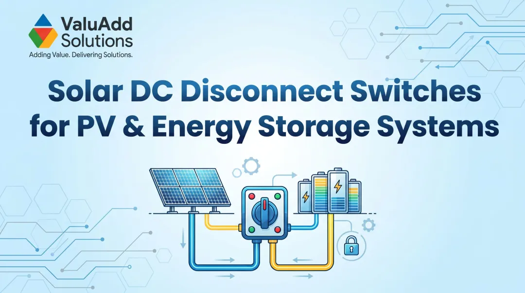
Introduction
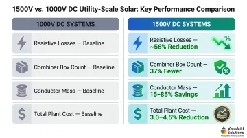
Utility-scale solar and battery energy storage systems (BESS) have rapidly standardized on 1500V DC architectures, and the economics are clear. Operating at 1500V reduces current by approximately 33% compared to 1000V systems, cutting resistive (I²R) losses by roughly 56% and slashing combiner box counts by 25-60%. This efficiency gain, however, comes with a non-negotiable safety requirement: every switching component in the DC circuit must be rated, tested, and certified specifically for 1500V DC load break — not simply voltage withstand, and never repurposed from AC service.
Specifying the wrong disconnect at 1500V DC can cause sustained arcing that destroys equipment, triggers cascading failures, or creates fire hazards. Unlike AC circuits, DC has no natural current zero-crossing to extinguish arcs — so proper load break capability is not a checkbox, it's a design requirement.
This guide explains what a 1500V DC load break switch is, how it differs from circuit breakers and isolators, which certifications matter, and how to select the right switch for solar or BESS applications.
TLDR:
- 1500V DC systems cut combiner boxes by 25–60% and resistive losses by ~56% vs. 1000V
- Load break switches safely interrupt full-load DC current; plain isolators cannot
- Require UL 98B (US) and IEC 60947-3 certification with Class DC-PV2 or DC-21/22 rating
- BESS demands explicit bi-directional switching capability; PV is typically unidirectional
- Verify IP65+ enclosure rating, 2-4 pole configuration, and 8,000+ mechanical cycle endurance
Why Utility-Scale Solar and BESS Systems Run on 1500V DC
The transition from 1000V to 1500V DC is complete for utility-scale projects. 1500V is now the de facto standard for utility-scale solar globally. Higher voltage means lower current for the same power output—which directly translates to reduced material costs and improved efficiency.
Efficiency and Cost Impact
Operating at 1500V DC reduces resistive losses by approximately 56%, achieving 26% lower resistive loss per circuit compared to 1000V. The infrastructure savings are substantial:
- Combiner boxes: 37% reduction in combiner box count for typical utility-scale configurations
- Conductor mass: 15-85% savings in DC cabling requirements
- Total plant cost: 3.0-4.5% reduction in overall utility-scale PV power plant costs
Longer string runs and fewer parallel strings per combiner drive these reductions—cutting combiner enclosure counts, land area, trenching, and labor per MW installed.
Component Compliance Mandate
Higher system voltage raises the bar for every component in the DC circuit. Disconnects and isolation switches must be rated, tested, and certified for 1500V DC interruption—not just voltage withstand.
A switch rated for 1500V AC or designed only for no-load isolation will fail catastrophically under load at 1500V DC. Arc energy at DC sustains indefinitely without the natural current zeros that AC provides every 8.3 milliseconds at 60 Hz.
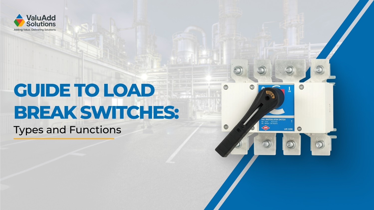
What Is a DC Load Break Switch—and Why "Load Break" Matters
The Critical Distinction
A DC load break switch is a manually or motor-operated switching device designed to make and break a DC circuit under full load conditions without causing destructive arcing. The term "load break" is not marketing language: it's a functional certification that separates safe operational switches from dangerous misapplications.
Why DC Arcs Are Uniquely Hazardous:
Unlike alternating current (AC), direct current (DC) flows continuously in one direction with no natural current zero to assist in interruption (per this IEEE switchgear reference). In AC systems, voltage and current cross zero 120 times per second (at 60 Hz), giving the arc a natural opportunity to extinguish.
DC arcs have no such mechanism. Once established, they sustain indefinitely unless the switch actively generates an arc voltage (Uarc) greater than the source voltage (Usource) to force collapse.
This requires specialized arc management features:
- Arc chutes that lengthen and cool the plasma path
- Magnetic blowout coils that deflect the arc into extinguishing chambers
- Specific contact geometry designed to stretch and interrupt the arc rapidly
These features are mandatory at 1500V DC and are absent from simple isolators or AC-rated switches.
Load Break vs. Simple Isolation
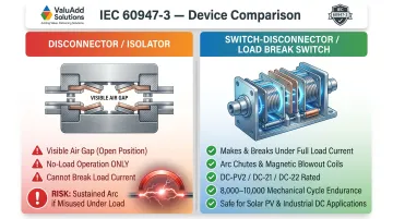
IEC 60947-3 distinguishes between two device types:
- Disconnectors (Isolators): Provide a visible air gap for isolation but are not designed to interrupt load currents; must only be operated under no-load conditions
- Switch-Disconnectors (Load Break Switches): Combine the ability to make, carry, and break currents under normal load conditions while providing isolation when open
Using a plain isolator under load at 1500V DC risks a sustained arc that can destroy the switch, damage adjacent equipment, ignite cable insulation, or cause personnel injury.
A true load break switch certified to IEC 60947-3 categories such as DC-PV2 or DC-21/22 guarantees the device can perform a defined number of load-break operations, typically 8,000–10,000 mechanical cycles under rated load.
System Architecture Placement
Understanding this functional distinction matters because placement drives selection criteria. In utility-scale systems, 1500V DC load break switches are located at:
- String-level: Within combiner boxes for individual string isolation
- Array-level: Between combiners and inverter for array-wide disconnect
- Main DC disconnect: As the primary disconnect point mandated by NEC Article 690
Each location serves a different role, distinct from string fuses (overcurrent protection) and DC circuit breakers (fault interruption). The load break switch handles planned operational switching, such as commissioning, maintenance isolation, and emergency shutdown, not automatic fault clearing.
Load Break Switch vs. Circuit Breaker at 1500V DC
A load break switch is optimized for intentional operational switching: turning circuits on and off under normal load. It is not designed to interrupt fault or short-circuit currents.
A circuit breaker is designed to automatically detect and interrupt overcurrent and fault conditions, often with electronic trip logic. Circuit breakers are not optimized for frequent manual switching operations.
When to Use Each:
- Load break switches: Planned isolation for maintenance, commissioning, and operational disconnect
- Circuit breakers or fuses: Overcurrent protection and fault interruption
In most 1500V DC systems, both devices are present: the switch for operational isolation (often motor-operated for remote control), the breaker or fuse for fault protection. This dual-device approach ensures safe O&M access while maintaining automatic protection against fault conditions.
Key Specifications for a 1500V DC Load Break Switch
Voltage and Current Ratings
The switch must carry a DC voltage rating of 1500V—not an AC voltage rating derated for DC use. DC-specific ratings differ fundamentally because DC arcs do not self-extinguish like AC arcs.
What to Verify on the Datasheet:
- Rated operating voltage (Ue): Must explicitly state 1500V DC (not "1500V AC/DC")
- Rated operating current (In): Must match or exceed the maximum expected string or array current (e.g., 1200A for large combiner applications)
- Peak make current: The switch must handle inrush current when closing onto live circuits, critical for BESS with capacitive loads
ValuAdd's SIRCO MOT DC ESS is rated for 1500 VDC and 2000A, with a short-circuit rating of up to 210 kA—specifications that cover the upper range of utility-scale combiner and BESS applications.
Certifications and Standards to Verify
For US Projects:
- UL 98B: The revised 2024 edition covers enclosed switches rated up to 2000V DC for photovoltaic systems. UL listing is typically required by the Authority Having Jurisdiction (AHJ) for utility-scale projects in the US.
For International Projects:
- IEC 60947-3:2020: Governs switches, disconnectors, and switch-disconnectors for circuits up to 1500V DC. The 2020 edition adds critical load current tests (clause 9.3.9) that older editions lacked.
Utilization Categories:
Verify the switch carries a DC-specific utilization category:
- DC-PV2: Specific to PV/BESS, handling single or dual polarity switching
- DC-21A/B: Switching of inductive loads
- DC-22A/B: Switching of mixed resistive and inductive loads with moderate overloads
ValuAdd's INOSYS LBS UL 98B and SIRCO MOT DC ESS both carry UL 98B listing and IEC 60947-3 certification.
Number of Poles and DC Circuit Configuration
DC systems require that all poles in series interrupt the arc. Unlike single-pole AC breakers, 1500V DC switches typically require:
- 2-pole configuration: For ungrounded (floating) DC systems, where both positive and negative conductors must be switched simultaneously
- 4-pole configuration: For grounded DC systems or where additional isolation is required for safety or monitoring
Grounded vs. Ungrounded:
- Ungrounded systems: No intentional connection to ground; both poles must open to de-energize the circuit
- Grounded systems: One conductor is bonded to ground, but NEC Article 690 still requires all ungrounded conductors to be switched
ValuAdd offers 2-pole, 3-pole, and 4-pole configurations to accommodate various system grounding schemes.
Enclosure and Environmental Rating
Utility-scale installations are outdoors, exposed to dust, moisture, UV radiation, temperature swings, and in some cases, corrosive atmospheres (coastal, industrial).
Minimum Requirements:
| Rating | Protection Level | Best Application |
|---|---|---|
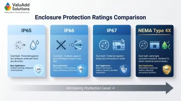
| IP65 | Dust-tight; protects against low-pressure water jets (12.5 L/min) | Standard outdoor enclosures |
| IP66 | Dust-tight; protects against powerful water jets (100 L/min) | High-pressure washdown areas |
| IP67 | Dust-tight; protects against temporary immersion (1 m, 30 min) | Flood-prone installations |
| NEMA Type 4X | Protects against windblown dust, hose-directed water, and corrosion | Coastal or industrial-adjacent sites |
ValuAdd's 1500V DC switches are tested against salt spray, humidity cycles, and temperature extremes to meet the demands of coastal and industrial-adjacent sites.
Mechanical and Electrical Endurance Ratings
Enclosure protection only matters if the switch mechanism itself lasts. Utility-scale assets are modeled for 25-30 year operational life, meaning load break switches must survive thousands of cycles—for commissioning, maintenance, and fault isolation—without contact degradation.
Typical Utility-Scale Endurance:
- Mechanical endurance: 8,000-10,000 operating cycles minimum (leading products exceed this)
- Electrical endurance: Verified through IEC 60947-3 load break tests at rated current
ValuAdd's SIRCO MOT DC ESS and INOSYS LBS UL 98B use durable contact materials and arc management systems verified to maintain performance across decades of field use.
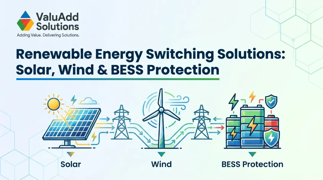
Solar vs. BESS: Different Switching Demands at 1500V
Solar-Specific Demand
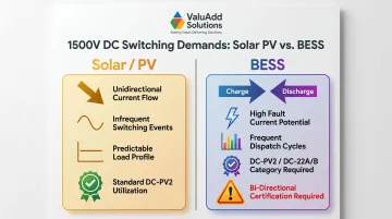
In photovoltaic string combiner applications, current flows unidirectionally—from the PV array to the inverter. The load break switch primarily handles planned isolation for:
- String commissioning and testing
- Maintenance access for module or combiner repairs
- Fault isolation to de-energize a failed string
The switching profile is relatively predictable, with infrequent operations (dozens to hundreds over the project life) and consistent unidirectional current flow.
BESS-Specific Challenge
Battery energy storage systems introduce distinctly different demands:
- Charge and discharge cycles reverse current direction — switches must be explicitly rated for bi-directional load break
- Battery banks can supply massive fault currents (tens to hundreds of kA) with minimal impedance, far exceeding typical PV fault levels
- Dispatch cycles, grid response, and maintenance operations produce far more switching events than typical PV applications
Critical Specification Point:
Not all 1500V DC switches rated for unidirectional PV applications are suitable for BESS. The datasheet must explicitly confirm bi-directional DC load break capability and appropriate utilization categories (DC-PV2 or DC-22A/B) for mixed resistive and inductive loads.
That distinction becomes even more consequential on co-located sites, where a single project may include both circuit types.
Hybrid Solar-Plus-Storage Projects
Engineers specifying switches for co-located solar and storage must verify:
- Can the same switch model serve both PV and BESS circuits, or are separate switch types required?
- What is the rated short-circuit withstand for the BESS side, where the battery bank delivers substantially higher fault energy?
ValuAdd's technical support team provides guidance for hybrid projects, helping system integrators and EPCs select appropriate switch configurations for each circuit type.
How to Select the Right 1500V DC Load Break Switch for Your Project
Specification Checklist Approach
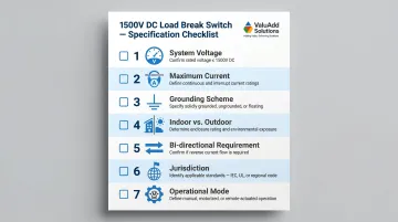
Before selecting a switch, answer these core questions:
- System voltage: 1500V DC (verify max open-circuit voltage under cold conditions)
- Maximum current: Peak string or array current, including any overload factor
- Grounding scheme: Ungrounded (floating) or grounded; determines pole configuration
- Indoor vs. outdoor: Enclosure IP/NEMA rating requirements
- Bi-directional requirement: PV-only (unidirectional) or BESS (bi-directional)?
- Jurisdiction: US (UL 98B required) or international (IEC 60947-3 required)
- Operational mode: Manual handle or motor-operated (remote control from SCADA/control room)
Evaluate Certifications Against Project Requirements
For US Utility-Scale Projects:
- UL 98B listing is mandatory for AHJ approval in most jurisdictions
- Verify the switch is listed under UL 98B Guide WHVA (not just components tested to UL standards)
For International Projects:
- IEC 60947-3 compliance is standard; verify the 2020 edition with clause 9.3.9 critical load testing
- CE marking confirms compliance with EU directives for electrical equipment
Common Mistake:
Selecting a switch with only an AC rating or without explicit DC load break certification (e.g., a plain isolator) is a costly and dangerous error at 1500V. The switch must carry both voltage rating and utilization category verification.
Long-Term O&M Factors
Field Usability:
- Visible position indicator with color-coded or labeled ON/OFF markings for fast, unambiguous status confirmation
- Padlockable handle to meet Lockout/Tagout (LOTO) requirements under OSHA 1910.147 and NEC Article 690
- Tool-free or single-motion actuation that reduces time and complexity for field technicians
Spare Parts and Support:
- Confirm replacement contact sets, arc chutes, and actuators are available through the full 10-15 year project life
- Verify the vendor offers technical support for troubleshooting and configuration changes throughout the asset lifecycle
Vendor and Supply Chain Considerations
Lead Times:
For utility-scale procurement, lead times can range from 8-16 weeks for large quantities or custom configurations. Early engagement with the supplier is essential to avoid schedule delays.
Factory Test Documentation:
Verify that the vendor provides:
- UL certificate of compliance
- IEC test reports (if applicable)
- Factory acceptance test (FAT) results for large orders
- Certificate of conformance
Single-Source Advantage:
Working with a supplier that provides IP-rated, UL-listed, Class DC-PV2-certified switches from a single source streamlines procurement, reduces coordination overhead, and ensures compatibility across the DC switching architecture. ValuAdd supports EPCs and system integrators through this process — including pole count selection, enclosure ratings, and motor-operated configurations for SCADA integration.
Frequently Asked Questions
What is the difference between a circuit breaker and a load break switch?
A load break switch is designed for planned operational switching under load but cannot interrupt fault currents. A circuit breaker automatically interrupts overcurrent and fault conditions. Both may be present in a 1500V DC system—the switch for operational isolation, the breaker for fault protection.
What are the different types of load break switches?
Main types include manual rotary switches, motor-operated switches for SCADA integration, fused load break switches that combine isolation and overcurrent protection, and modular string-level switches for combiner boxes. All must be DC-rated at 1500V with appropriate utilization categories.
What are the requirements for solar system disconnect?
NEC Article 690 requires a readily accessible, lockable DC disconnect on the PV output circuit. The disconnect must be rated for the system's maximum DC voltage and current and must interrupt all ungrounded conductors. The switch must provide a visible open gap and allow for LOTO procedures.
Can a load break switch be used for battery energy storage systems (BESS)?
Yes, provided the switch carries an explicit bi-directional DC load break rating at the required voltage and current. Switches rated only for unidirectional PV use are not suitable for BESS—verify the DC-PV2 or DC-22A/B utilization category on the datasheet before specifying.
What certifications should a 1500V DC load break switch have for utility-scale solar?
Key certifications include UL 98B or UL Listed status for US projects, IEC 60947-3 compliance with DC utilization categories (DC-PV2, DC-21/22), and an appropriate IP/NEMA enclosure rating (minimum IP65 for outdoor installations, NEMA Type 4X for corrosive environments). Verify both electrical endurance and mechanical cycle ratings.
What voltage rating do I need for a DC load break switch in a 1500V solar system?
The switch must carry a native DC voltage rating of 1500V—not an AC rating. Current rating must meet or exceed the maximum operating current of the string or array circuit. Never rely on AC ratings derated for DC use; DC arc interruption physics are distinct from AC and require separate validation.