Introduction
DC circuits in solar PV and energy storage systems present a hazard that AC systems don't: persistent voltage with no natural interruption point. A photovoltaic array generates dangerous voltage whenever light strikes the modules—regardless of whether the inverter is operating. Battery banks stay live continuously. Unlike AC circuits, where natural zero-crossings allow current to safely interrupt every half-cycle, DC arcs can persist and reach temperatures up to 15,000°C. Purpose-built DC disconnect switches are a mandatory safety and code compliance requirement—not an optional upgrade.
This guide covers both PV array DC disconnects (NEC Article 690) and energy storage system (ESS) DC disconnects (NEC Article 706). Whether you're specifying for a commercial rooftop or a utility-scale storage installation, you'll find:
- Sizing methodology based on open-circuit voltage and short-circuit current
- Labeling requirements that satisfy inspectors and first responders
- Key specification criteria: voltage rating, interrupting capacity, Class E2 load break capability, and enclosure ratings
Key Takeaways
- DC disconnect switches safely isolate PV arrays or battery banks from inverters and loads during maintenance, emergencies, or grid events
- NEC 690.8 requires sizing at 125% of short-circuit current; NEC 706.15 mandates ESS disconnects be within sight, lockable, and fault-current labeled
- Size voltage ratings with 15% headroom above calculated Voc — 1000 VDC for rooftop, 1500 VDC for ground-mount utility systems
- Select UL 98B-listed devices with Class E2 load break certification and NEMA 4X/IP66 enclosures for outdoor installations
- Bidirectional ESS applications require switches rated for fault currents up to 10 kA or higher in both charge and discharge directions
What Is a Solar DC Disconnect Switch and Where Does It Fit?
Defining the DC Disconnect Switch
A DC disconnect switch is a manually or automatically operated switching device that safely interrupts direct current flow in a PV or ESS circuit.
The critical distinction from AC: DC circuits lack a natural zero-crossing, allowing arcs to persist. That means DC-rated devices must include specialized arc-extinguishing mechanisms—magnetic blowouts, arc chutes, and de-ion grids—that standard AC-rated switches simply don't have. Installing an AC switch in a DC circuit creates genuine arc flash and fire risk.
System Placement and Architecture
For PV systems, the DC disconnect (also called a PV disconnect or array disconnect) installs between the solar array output or combiner box and the inverter input. Some modern string inverters integrate a DC disconnect internally, which simplifies balance-of-system design.
Battery storage systems require a separate disconnecting means between the battery bank and the inverter or load center. Batteries present unique hazards: they're always energized, bidirectional (charge and discharge), and capable of extremely high fault currents.
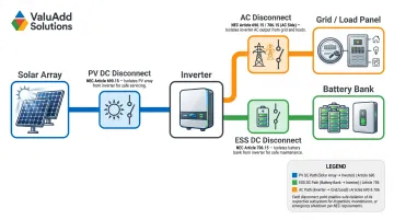
A solar-plus-storage system combines both requirements. You'll find three distinct disconnects in these installations:
- PV DC disconnect — isolates the solar array
- ESS DC disconnect — isolates the battery bank
- AC disconnect — isolates the inverter output from the grid or load
All three are required by code (NEC Article 690 for PV, Article 706 for ESS), and none can substitute for the others — each targets a distinct point of isolation in the system.
NEC Code Requirements for PV DC Disconnects
NEC 690.13 — Disconnecting Means Required
NEC 690.13 mandates that every PV system have a disconnecting means to isolate all ungrounded DC conductors from the system. Key requirements:
- Must be readily accessible or lockable-open per NEC 110.25
- Shall consist of not more than six switches or six sets of circuit breakers
- Must be permanently marked "PV SYSTEM DISCONNECT"
- Must plainly indicate open (off) or closed (on) position
- Typically installed on building exteriors for first responder access
NEC 690.8 — Current Sizing Rule
NEC 690.8(A) states: "The maximum current shall be the sum of parallel module rated short-circuit currents (Isc) multiplied by 125%."
This 125% multiplier accounts for irradiance conditions that can exceed standard test conditions (STC). Real-world solar insolation can spike above 1000 W/m² due to cloud-edge effects and ground reflection.
NEC 690.8(B) then requires conductor ampacity to be at least 125% of the 690.8(A) current—resulting in a cumulative 156% multiplier. The DC disconnect itself, however, must meet only the 125% multiplier from 690.8(A).
NEC 690.7 — Maximum Voltage
Once current is sized, voltage rating is the other critical dimension. Maximum system voltage is calculated by summing the open-circuit voltage (Voc) of series-connected modules and correcting for low-temperature conditions, since colder temperatures increase Voc.
Formula:
Corrected Voc = Voc(STC) × [1 + (Lowest Temp °C – 25°C) × (Temp. Coefficient of Voc %/°C)]
Voltage limits:
- 1000 VDC maximum for circuits on or attached to commercial/multifamily buildings
- Up to 1500 VDC for ground-mounted or exterior installations less than 10 feet above grade per NEC 690.31(G)
Industry best practice: select a disconnect with at least 15% voltage headroom above calculated Voc.
NEC 690.15 — Disconnecting Means for Equipment
NEC 690.15 requires disconnecting means to isolate individual inverters, charge controllers, and converters from all ungrounded conductors. In multi-inverter commercial installations, this means each inverter needs its own equipment disconnect—separate from the main PV system disconnect.
Rapid Shutdown (NEC 690.12)
Rapid shutdown is a related but distinct requirement. NEC 690.12 mandates that controlled conductors be limited to ≤30 volts (outside the array boundary) or ≤80 volts (inside the array boundary) within 30 seconds of initiating shutdown.
Rapid shutdown does not replace the DC disconnect requirement. Many modern systems integrate rapid shutdown into the disconnect design, but the two remain separate code provisions.
DC Disconnect Switches for Energy Storage Systems
What Is an ESS Disconnect?
An ESS disconnect is a disconnecting means required by NEC Article 706 that allows an energy storage system—typically a battery bank—to be safely isolated from the rest of the electrical system. Unlike PV arrays that go dark at night, batteries store energy continuously and present live voltage at all times. That distinction makes the disconnect requirement especially demanding:
- Batteries are always energized
- Current flows bidirectionally (charge and discharge)
- Available fault currents can be extremely high (lithium-ion ESS can deliver 10+ kA short-circuit current)
- Thermal runaway events make accessible, clearly labeled disconnects a life-safety priority for first responders
NEC 706.15 — ESS Disconnecting Means Requirements
- Accessibility: Must be readily accessible
- Proximity: Must comply with one or more of: (1) Located within the ESS; (2) Visible and within 10 feet from the ESS; (3) Where not within sight, lockable-open per 110.25
- Interruption: Must simultaneously disconnect all ungrounded conductors
- Ratings: Must be rated for maximum circuit current, available fault current, and voltage at the terminals
NEC 110.9 requires equipment intended to interrupt fault currents to have an interrupting rating at least equal to the available fault current at the line terminals.
What Must Be Indicated on the Disconnecting Means of an ESS
Per NEC 706.15 and labeling provisions, the ESS disconnect must display:
- System voltage (nominal battery voltage)
- Rated current
- Available fault current and arc-flash label (for non-dwelling units)
- Date the fault current calculation was performed
- Current directionality where applicable
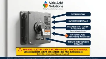
If line and load terminals can be energized in the open position, a warning sign must state: "WARNING ELECTRIC SHOCK HAZARD TERMINALS ON THE LINE AND LOAD SIDES MAY BE ENERGIZED IN THE OPEN POSITION."
Labeling requirements extend beyond NEC for larger installations. NFPA 855 (Standard for the Installation of Stationary Energy Storage Systems) may require additional placards identifying ESS type, capacity, and emergency contact information for commercial and industrial sites.
NEC 2026 Emergency Disconnect Requirement
The draft NEC 2026 introduces a new provision requiring a readily accessible, single-operation emergency disconnect for qualifying ESS installations above a defined capacity or voltage threshold. This emergency disconnect must be:
- Operable without special tools
- Accessible to emergency responders
- Distinct from the standard disconnecting means under NEC 706.15
Specific thresholds and section numbering are still being finalized in the 2026 code cycle. The goal is straightforward: give first responders a single, tool-free shutoff point during thermal runaway or other emergencies—without working through multi-step isolation procedures.
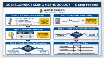
How to Size a Solar DC Disconnect Switch
Step 1 — Determine Maximum System Voltage
- Multiply the Voc (STC) of one module by the number of series-connected modules per string
- Apply a low-temperature correction factor based on the coldest expected ambient temperature at the installation site
- The result must not exceed the disconnect switch's rated voltage
Best practice: Select a switch with at least 15% voltage headroom above calculated Voc to account for measurement uncertainty and module performance variation.
Step 2 — Calculate Required Current Rating
- Sum the ISC of all parallel-connected strings to determine total array ISC
- Multiply by 1.25 per NEC 690.8 to obtain minimum required ampacity
Example:
20 parallel strings × 7.92 A ISC = 158.4 A
158.4 A × 1.25 = 198 A minimum rating
Step 3 — Apply Temperature Derating
If the disconnect will be installed where ambient temperatures exceed the device's rated temperature (typically rated to 40°C), apply a derating factor to the nameplate rating. For example, ABB Emax 2 MS/DC-E 2500A switches maintain 100% capacity up to 55°C but derate to 95% at 60°C and 85% at 70°C.
To calculate the minimum nameplate rating: Divide the required current by the derating factor.
Example: If you need 200A continuous and the device derates to 0.85 at 70°C, you need a switch rated for at least 200A ÷ 0.85 = 235A nameplate.
ValuAdd's INOSYS LBS UL 98B switches are rated for full continuous current up to 131°F (55°C), eliminating the need to upsize nameplate ratings for most outdoor installations.
Step 4 — Fused vs. Non-Fused Disconnect
NEC 690.9 requires overcurrent protection when more than two parallel module strings feed a single circuit. For systems with two or fewer strings, a non-fused disconnect may be acceptable — provided no external backfeed sources (batteries, grid-tied inverters) exist.
Continuous operation rating:
Equipment must be rated for continuous operation at 100% of nameplate current. Some devices are only rated at 80% continuous, which affects sizing. Verify the manufacturer's continuous duty rating before specifying.
Step 5 — Number of Poles
Ungrounded systems (typical of modern transformerless inverters): Both positive and negative conductors must be interrupted, requiring a 2-pole disconnect.
Grounded systems: May only require interruption of the ungrounded conductor, but confirm requirements with the local authority having jurisdiction (AHJ) before specifying.
ValuAdd's INOSYS LBS UL 98B is available in 1-pole, 2-pole, 3-pole, and combination configurations (1+1 and 2+2) to match either grounded or ungrounded system architectures.
Choosing the Right DC Disconnect: Key Specs and Certifications
Electrical Certifications and Load Break Rating
UL 98B: The primary standard for PV DC disconnect switches up to 2000 VDC. This standard specifically modifies UL 98 for DC applications and tests devices for DC interruption duty.
Class E2 Load Break Rating: Certifies the switch can safely interrupt load current—not just isolate a de-energized circuit. This is critical for maintenance scenarios where the array may still be generating. IEC 60947-3 defines utilization categories based on load types (e.g., DC-21A for inductive loads, DC-22A for mixed loads).
Why this matters: Standard AC switches lack the arc-extinguishing mechanisms required for DC—magnetic blow-out coils, arc chutes, de-ion grids—that safely interrupt sustained DC plasma arcs.
Environmental Enclosure Rating
For outdoor PV installations and battery enclosures:
- IP66: Jet-water resistant, protects against powerful jetting water
- IP68: Submersion rated for continuous immersion under manufacturer-specified conditions
- NEMA Type 4X: Corrosion-resistant, exceeds IP66 by adding corrosion and icing tests
NEMA 4X exceeds IP66 requirements, making it superior for harsh outdoor environments—coastal installations, chemical processing facilities, and industrial rooftops exposed to washdown.
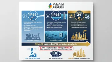
Important: The NEMA-to-IP relationship cannot be reversed. A product meeting IP66 does not automatically satisfy NEMA 4X.
ValuAdd's DC Disconnect Switch Portfolio
ValuAdd's DC disconnect switches meet all the criteria above: UL 98B listing, Class E2 load break certification, IP66/IP68 ratings, and NEMA Type 4X compliance. These specifications make them a direct fit for rooftop commercial PV, ground-mount utility, and industrial energy storage applications where environmental protection and verified interrupting capacity are non-negotiable.
SIRCO MOT DC ESS
- Rated up to 1500 VDC and 2000 A
- Short-circuit rating up to 210 kA
- Motorized remote operation for enhanced safety
- Certified to UL 98B, IEC 60947-3, GB/T 14048.3
- Designed for harsh environments with salt spray, high temperature, and humidity testing
INOSYS LBS UL 98B
- Rated 10A to 1200A, up to 1500 VDC
- Breaking capacity 750 VDC per pole
- Modular design for single or dual polarity switching
- No derating required up to 131°F (55°C)
- Visible contacts with arc fault containment
Both models support bidirectional current flow, so they handle ESS charge and discharge cycles without derating or additional hardware.
Frequently Asked Questions
What are the NEC requirements for PV disconnect?
NEC 690.13 requires every PV system to have a disconnecting means for all ungrounded DC conductors, accessible and externally operable, typically marked "PV SYSTEM DISCONNECT." NEC 690.8 requires the device be rated for at least 125% of the system's calculated short-circuit current.
What is an ESS disconnect?
An ESS disconnect is a switching device required by NEC Article 706 that safely isolates a battery-based energy storage system from the rest of the electrical installation. It must be rated for available fault current and remain accessible — or lockable — in the open position.
What should be indicated on the disconnecting means of an ESS?
Per NEC 706.15, required markings include system voltage, rated current, available fault current (for non-dwellings), and current directionality where applicable. NFPA 855 adds further placard requirements covering ESS type, storage capacity, and emergency contact information.
What is the NEC 2026 emergency disconnect?
The draft NEC 2026 requires a readily accessible, single-operation emergency disconnect for qualifying ESS installations, allowing first responders to de-energize the system quickly without special tools. This differs from the standard disconnecting means already required under NEC 706.15.
How do you size a DC disconnect for a solar PV system?
Voltage rating must exceed the maximum open-circuit voltage (Voc) of all series-connected modules, corrected for minimum expected temperature. Current rating must be at least 125% of the total array short-circuit current — calculated as the sum of parallel string ISC values — per NEC 690.8.
What is the difference between a fused and non-fused DC disconnect?
A fused DC disconnect incorporates overcurrent protection within the switch enclosure and is required when more than two parallel strings feed a circuit. A non-fused disconnect provides isolation only and is used where separate fusing or overcurrent protection is already installed upstream.