Industrial operators, system integrators, and facility engineers need switching solutions engineered specifically for each technology. Selection hinges on four critical factors: voltage class matching the system's operating parameters, interrupt capacity adequate for maximum available fault current, environmental protection ratings suited to installation conditions, and strict code compliance with NEC Articles 690, 694, and 706.
This guide examines the specialized requirements for solar PV disconnects—both DC and AC—wind energy switching across collection system voltage levels, and BESS protection addressing bidirectional flows and thermal runaway isolation.
Key Takeaways
- Solar PV DC disconnects must be rated for temperature-corrected open-circuit voltage (1000–1500 VDC) and meet NEC 690.13 accessibility rules
- Wind systems span three voltage tiers — 690V turbine output, 34.5 kV collection, and grid interconnection — each requiring distinct switching gear
- BESS switching must handle bidirectional DC at 1000–1500 VDC with interrupt ratings covering fault currents above 79 kA
- Outdoor enclosures need IP65/IP66 or NEMA 4X minimum to survive temperature swings, moisture, and vibration
- IEEE 519 limits harmonic distortion to below 8% THDv at the point of common coupling
Why Renewable Energy Systems Demand Specialized Switching Solutions
Conventional AC switching technology is inadequate for renewables because DC power from solar and storage lacks natural zero-crossings. In AC circuits, current passes through zero voltage 120 times per second, providing natural arc extinction points when contacts separate.
DC circuits have no such zero-crossing. Arc extinction during disconnection requires specialized contact materials like silver tin oxide (AgSnO₂), magnetic blowout coils that deflect arcs into arc chutes, and extended contact gaps—up to 12mm for 1500V systems.
The always-on nature of renewable sources makes multi-point isolation mandatory. Each source type presents its own persistent hazard:
- Solar arrays produce voltage in daylight regardless of inverter state, creating "stranded energy" hazards for first responders
- Wind turbines cannot be instantly de-energized due to mechanical inertia
- BESS installations hold stored energy that persists during grid outages, requiring isolation before any maintenance access
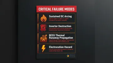
Key failure modes that proper switching prevents:
- Sustained DC arcing leading to enclosure fires and equipment damage
- Inverter destruction from improper isolation during maintenance
- BESS thermal runaway propagation when faults cannot be contained at module level
- Electrocution hazards for maintenance personnel and emergency responders accessing energized systems
These hazards are exactly what the US regulatory framework is designed to address. NEC Article 690 (solar), Article 694 (wind), and Article 706 (energy storage) set the mandatory switching and isolation requirements for each source type. IEEE 519-2022 enforces harmonic compliance at grid interconnection points, limiting steady-state voltage distortion below 8% THDv and current distortion below 5% TDDi. UL/NEMA/IP environmental ratings then define physical protection levels for outdoor and harsh-environment installations.
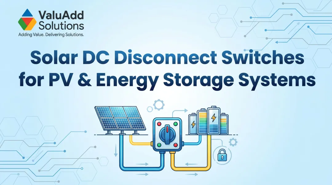
Solar PV Switching: DC Disconnects, AC Disconnects, and Rapid Shutdown
DC Disconnects: Isolating the Array
DC disconnects installed between the PV array output and the inverter must interrupt direct current that does not self-extinguish. Voltage ratings must meet or exceed maximum open-circuit voltage (Voc)—calculated at the lowest expected ambient temperature using NEC Table 690.7(A) correction factors.
For example, modules rated at 45V Voc with a temperature coefficient of -0.29%/°C installed in a location with a -20°C design minimum would require: 45V × (1 + 0.29% × 40°C) = 50.2V per module.
Continuous current ratings must be 125% of short-circuit current (Isc) per NEC 690.8. A string with 12A Isc requires a disconnect rated for at least 15A continuous duty.
Load-break vs. non-load-break configurations:
- Load-break switches can safely interrupt current under operating conditions and are preferred for locations where the switch may be opened while the array generates power
- Non-load-break (isolator) switches require a "DO NOT OPEN UNDER LOAD" warning label and may only be used after upstream current interruption
Fused vs. non-fused DC disconnects:
- Fused disconnects combine overcurrent protection and isolation in one enclosure (DC-rated fuses are not interchangeable with AC fuses)
- Non-fused disconnects are appropriate when upstream overcurrent protection already exists
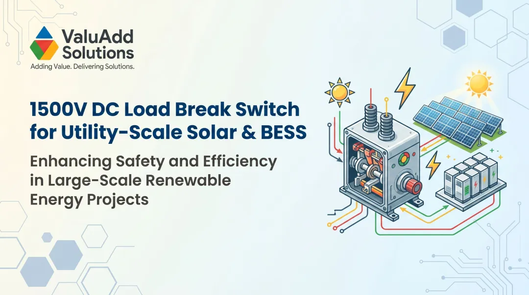
Voltage class selection also depends on the installation tier. 1500 VDC has become the standard for utility-scale PV, reducing component count and lowering Balance of System (BOS) costs, while commercial installations commonly use 1000 VDC systems. ValuAdd's SIRCO MOT DC ESS disconnect switch supports up to 1500 VDC and 2000A, with a short-circuit rating of 210 kA — suited for the fault-current demands of utility-scale solar arrays.
AC Disconnects: Inverter-to-Grid Isolation
The AC disconnect between the inverter output and the utility meter uses standard AC interrupting mechanisms that rely on the current's natural zero-crossing, making design simpler than DC switches. NEC 690.13 and 705.12/705.20 govern placement—disconnects must be readily accessible (mounted 4.5–6.5 ft above grade) and visible to utility personnel without entering the building.
Key AC disconnect design requirements include:
- Mounted between 4.5–6.5 ft above grade for ready access
- Visible to utility personnel without building entry (NEC 705.20)
- Rated for inverter output voltage and continuous AC current
Rapid Shutdown Requirements
NEC 690.12 mandates that PV systems on buildings reduce array voltage to 80V or less within 30 seconds of shutdown initiation. The 2023 NEC clarified that PV equipment installed on non-enclosed detached structures (like carports) are exempt from these requirements.
Implementation options include:
- Module-level power electronics (optimizers, microinverters)
- String-level rapid shutdown devices
- Enhanced system-level disconnects with integrated rapid shutdown functionality
Wind Energy Switching: Turbine-Level and Collection System Protection
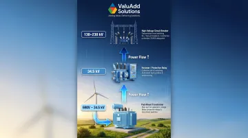
Wind energy switching operates at multiple levels, each requiring different technology. At the turbine level, a contactor or circuit breaker isolates the generator from the step-up transformer. Transformers step up generation voltage (typically 690V) to medium voltage, commonly 34.5 kV, which is preferred because standardized equipment is available and higher voltage transformers would be too large for tower cross-sections. At the substation level, high-voltage switching connects the wind farm to the transmission grid.
Variable-speed turbines using doubly-fed induction generators (DFIG) or full converters introduce complex challenges. Power converters using pulse width modulation (PWM) switching produce harmonics, including low-order harmonics (5th, 7th, 11th, and 13th) as well as higher orders (39th and 41st).
These non-sinusoidal currents cause thermal stress and overheating in switchgear, potentially altering protective relay operating times.
Switching solutions must be IEEE 519 compliant at the point of common coupling and capable of interrupting the asymmetric fault currents characteristic of converter-based generation. ValuAdd's switching components address this directly — controlling harmonic distortion to less than 8% THDv through 18-pulse designs with phase-shifting transformers.
Environmental Protection for Wind Farm Switchgear
Wind farms in exposed, remote locations face temperature extremes, humidity, salt spray (offshore), and vibration. IP65/IP66 minimum or NEMA 4X enclosures with vibration-rated components are required for reliable operation in these conditions. ValuAdd's switching products carry IP65/IP66/IP68 and NEMA 4X certifications, meeting the stringent requirements for wind farm nacelle and tower-base installations.
| Wind Farm Level | Typical Voltage | Switching Technology |
|---|---|---|
| Turbine (Nacelle/Base) | 690V to 34.5 kV | Pad-mounted transformers, MV load break switches |
| Feeder/Collection | 34.5 kV | Reclosers, directional overcurrent relays, distance relays |
| Substation | 130-230 kV | High-voltage circuit breakers, reactive compensation |
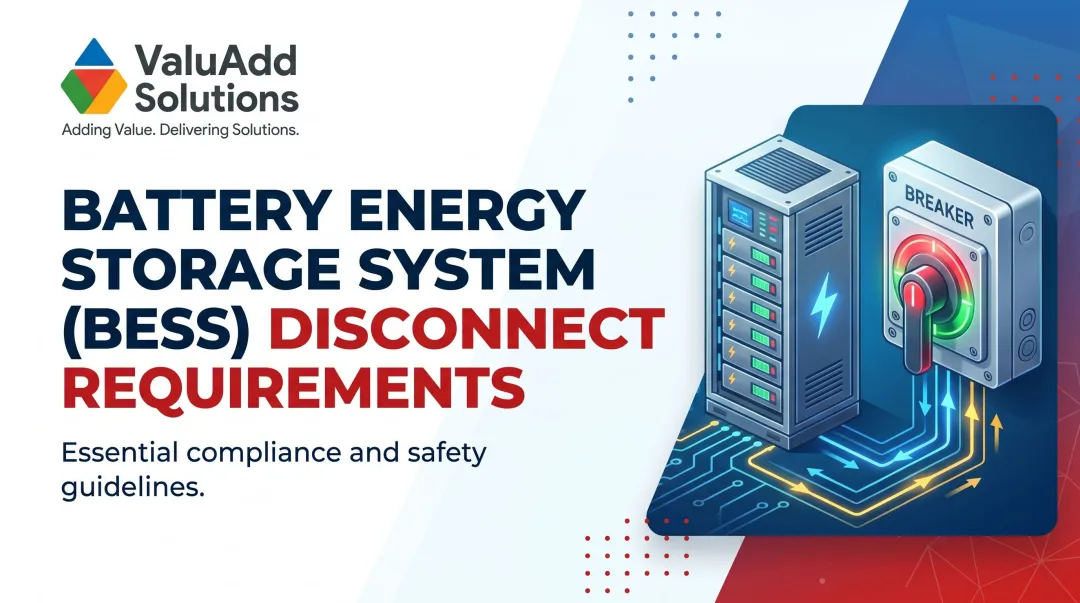
BESS Switching and Protection: Unique Challenges for Energy Storage
Energy storage systems are bidirectional—they absorb current during charging and deliver current during discharge. This requires switching devices rated for current flow in both directions, unlike unidirectional PV or wind disconnect switches. Large BESS installations can deliver instantaneous fault currents reaching 79-80 kA, demanding disconnect switches with correspondingly high ampere interrupting capacity (AIC) ratings.
The Thermal Runaway Isolation Challenge
Lithium-ion BESS installations face thermal runaway risk, where an electrochemical cell increases temperature through self-heating in an uncontrollable fashion, potentially leading to off-gassing, fire, or deflagration. Switching solutions must support cell-level, module-level, and system-level isolation to contain faults and prevent cascade failures.
BESS disconnect switches must operate reliably at elevated temperatures and during abnormal voltage transients produced by failing cells. ValuAdd's SIRCO MOT DC ESS switch has been tested for harsh environmental conditions, including high temperature and humidity cycles, ensuring reliable operation during thermal events.
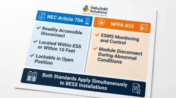
BESS-Specific Code Requirements
Two standards drive switching compliance for energy storage installations:
- NEC Article 706 requires a readily accessible disconnect capable of de-energizing the storage system from all power sources. The disconnect must be located within the ESS, within sight and within 10 feet of the ESS, or lockable in the open position.
- NFPA 855 mandates that energy storage management systems (ESMS) monitor and control performance, including the ability to disconnect modules during abnormal conditions.
DC Bus Voltage Considerations
Utility-scale BESS commonly operate at 1000-1500 VDC bus voltages to match PV systems and improve space efficiency. Switching components must be tested and rated for DC operation at these voltages, not adapted from AC-rated hardware.
That DC rating also affects fault analysis. Because BESS are inverter-based resources, their fault current characteristics differ from conventional synchronous generators, making site-specific short-circuit studies mandatory.
For BESS installations requiring IEEE 519-compliant grid interconnection, switching solutions must support harmonic monitoring at the point of coupling. ValuAdd's IEEE 519 compliant, UL Listed switching components provide a verified solution path for system integrators designing BESS interfaces that must meet both NEC 706 and grid interconnection harmonic standards.
How to Select Switching Solutions: Ratings, Standards, and Environment
Key Electrical Parameters to Specify
Specification checklist for renewable energy switching:
- Voltage rating — Must meet or exceed temperature-corrected Voc for solar (use NEC Table 690.7), line voltage class for wind collection, DC bus voltage for BESS
- Continuous current rating — Minimum 125% of maximum circuit current for solar per NEC 690.8, matched to rated operating current for wind and BESS
- AIC/interrupt rating — Must exceed available fault current at the point of installation based on site-specific short-circuit study
- Load-break vs. isolator duty — Confirm the switch can open safely under operating current unless upstream current interruption is guaranteed
Avoid universal AIC minimums—equipment evaluation must be based on site-specific studies that account for the unique fault contributions of inverter-based resources.
Environmental and Certification Requirements
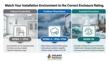
Outdoor renewable installations, including rooftop solar, wind farm pad-mounts, and utility BESS containers, require enclosures rated IP65 minimum for dust and water jet resistance, with IP66 or IP68 for fully exposed or submersion-risk sites. For US installations, NEMA 4X provides the equivalent corrosion-resistant, weatherproof standard, backed by rigorous salt spray testing for coastal or chemical environments. The table below maps common installation environments to their recommended enclosure ratings.
Enclosure ratings address physical protection, but the switching equipment itself must meet applicable electrical certification standards. Key certifications to require:
- UL Listed for the US market (UL 98B for DC switches, UL 98C for AC)
- CE for international projects
- Class E2 load break rating for switches that must interrupt full load current repeatedly without maintenance
- IEEE 519 compliance for grid interconnection applications
ValuAdd's switching products carry UL Listed, CE, IP65/IP66/IP68, NEMA 4X, and Class E2 load break certifications. The INOSYS LBS UL 98B delivers up to 1500 VDC breaking capacity (750 VDC per pole) under UL 98B and IEC 60947-3, while the SIRCO MOT DC ESS adds motorized operation for remote switching in utility-scale BESS applications.
| Environment | Recommended Enclosure | Key Selection Criteria |
|---|---|---|
| Indoor/Controlled | NEMA 1 / IP20 | Basic contact protection, adequate ventilation |
| Outdoor/Washdown | NEMA 4 / IP65 or IP66 | Protection against windblown dust and hose-directed water |
| Coastal/Corrosive | NEMA 4X | Corrosion resistance (stainless steel/fiberglass), salt spray tested |
Frequently Asked Questions
What does a solar disconnect switch do?
A solar disconnect switch interrupts power flow between the PV array, inverter, and utility grid, allowing safe maintenance, emergency shutdown, and first-responder access. NEC Article 690.13 requires it for all grid-tied solar installations to protect personnel from stranded energy hazards.
How is BESS switching different from solar PV switching?
BESS switching must handle bidirectional DC current flow (charging and discharging), higher instantaneous fault currents (79–80 kA vs. typical PV levels), thermal runaway isolation scenarios, and NEC 706/NFPA 855 requirements — demands that go well beyond unidirectional solar disconnect applications.
What voltage rating do I need for a solar DC disconnect switch?
The switch must be rated at or above the temperature-corrected open-circuit voltage of the array using NEC Table 690.7 correction factors. 1000 VDC is standard for most commercial systems, while 1500 VDC is required for utility-scale installations to optimize efficiency and reduce component counts.
What IP or NEMA rating is required for outdoor renewable energy switching equipment?
IP65 is the minimum for general outdoor applications (dust-tight, water-jet resistant), while IP66 is required for fully exposed environments. NEMA 4X is specified for corrosion-resistant installations in coastal, chemical, or industrial settings where salt spray and harsh conditions are present.
What is a Class E2 load break switch and why does it matter for renewable energy?
A Class E2 load break switch interrupts full load current repeatedly without overhaul or maintenance throughout its service life. This makes it essential for renewable energy disconnect points that may be opened under live conditions — unlike isolators, which require a de-energized circuit.
What standards govern wind energy switching at the collection system level?
Wind collection system switching is governed by NEC Article 694, ANSI/IEEE medium-voltage switching standards (IEC 62271 series), and utility interconnection requirements including IEEE 519 for harmonic limits at the point of common coupling. Voltage class and utility specifications often add site-specific requirements on top of these baselines.