Introduction
Busbar support and stand-off insulator spacing is technically demanding—while the components themselves are straightforward, incorrect spacing decisions compromise arc flash safety, mechanical integrity under short-circuit forces, and regulatory compliance. One documented failure analysis of a 6300A distribution panel showed what this looks like in practice: inadequate support spacing under electromagnetic forces (calculated at 4416.73 N) caused busbar deflection exceeding 64 mm, triggering a short circuit and total system failure.
That failure traces back to confusing two distinct spacing decisions—the most common and costly design error in busbar systems:
- Electrical clearance and creepage distance: the gap between live parts and ground that prevents arc-over between conductors
- Mechanical support interval spacing: the distance between insulators along the busbar run that prevents displacement during fault conditions
This guide covers how to determine, design, and install both correctly for industrial low-voltage and medium-voltage applications—aligned with NEC, IEC, and UL standards.
Key Takeaways
- Busbar spacing involves two separate calculations: electrical clearance (phase-to-phase and phase-to-ground) and mechanical support interval—address both independently
- Electrical clearance minimums depend on voltage level and bare vs. insulated busbars; NEC Table 408.56 and IEC 60664-1 are the governing references
- Mechanical support spacing (typically 300mm–500mm) must account for busbar weight, short-circuit electromagnetic forces, and vibration conditions
- Skipping post-installation validation (torque checks, visual clearance confirmation) means failures surface only under fault conditions
- Selecting correctly rated stand-off insulators (voltage class, mechanical load rating, material) is as critical as the spacing calculation itself
What Are Busbar Supports and Stand-Off Insulators?
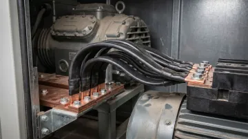
Busbar supports are mechanical brackets or clamps that secure busbars to an enclosure structure. Stand-off insulators are dielectric elements—typically epoxy resin, BMC, SMC, or ceramic—that provide both mechanical support and electrical isolation in a single component.
Many assemblies combine both functions, such as ValuAdd's SB1-SB2 Busbar Support, which uses M8 screw connections and UL94 V0 insulating materials.
Functional Difference
- Stand-off insulators maintain a fixed air gap between the busbar and mounting surface, creating required creepage and clearance distance
- Busbar support clamps hold the busbar's physical position against gravity, vibration, and electromagnetic forces generated during fault conditions
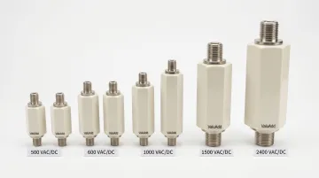
Both must work together for a compliant installation. For example, ValuAdd's Male-Female Hexagonal Insulators (rated 500–2400 VAC/VDC) provide electrical isolation while withstanding short-circuit forces, tested to IEC 61439-1 and IEC 60865-1 standards.
Selection depends on:
- Voltage rating and Basic Insulation Level (BIL)
- Number of phases (single, three, four, or five phase)
- Busbar cross-section dimensions and material (copper or aluminum)
- Phase-to-phase center distance
Getting these parameters right before installation prevents costly rework and keeps assemblies within code compliance.
Understanding the Two Types of Busbar Spacing
Electrical Clearance: Preventing Arc-Over
Electrical clearance is the minimum air gap between uninsulated conductive parts (phase-to-phase and phase-to-ground) that prevents arc-over. NEC Table 408.56 provides absolute minimums—installations should exceed them to accommodate vibration and thermal expansion.
NEC 408.56 Minimum Spacings for Uninsulated Busbars:
| AC or DC Voltage | Opposite Polarity (Same Surface) | Opposite Polarity (Free in Air) | Live Parts to Ground |
|---|---|---|---|
| Not over 125 V | 19.1 mm (3/4 in) | 12.7 mm (1/2 in) | 12.7 mm (1/2 in) |
| Not over 250 V | 31.8 mm (1-1/4 in) | 19.1 mm (3/4 in) | 12.7 mm (1/2 in) |
| Not over 1000 V | 50.8 mm (2 in) | 25.4 mm (1 in) | 25.4 mm (1 in) |
The "live parts to ground" requirement applies to all grounded metal surfaces, including the enclosure bottom.
Creepage Distance: Preventing Surface Tracking
Creepage distance is the minimum surface path distance along an insulator between live parts, preventing surface tracking under contamination or humidity. IEC 60664-1 Table F.4 provides creepage values for standard industrial environments.
IEC 60664-1 Creepage Distances (Material Group II):
| Rated Insulation Voltage (Ui) | Pollution Degree 1 | Pollution Degree 2 | Pollution Degree 3 |
|---|---|---|---|
| 400 V | 1.0 mm | 2.0 mm | 2.8 mm |
| 800 V | 2.4 mm | 4.0 mm | 5.6 mm |
| 1000 V | 3.2 mm | 5.0 mm | 7.1 mm |
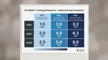
When to use Pollution Degree 3: Outdoor installations, oil and gas facilities, water treatment plants—environments with conductive pollution or condensation require significantly larger creepage distances.
How Insulation Changes the Equation
Once creepage requirements are understood, the conductor's insulation type directly affects how much air clearance you can reduce. Insulated busbars can operate with reduced air clearance to the enclosure structure, but the insulation material must meet IEC 60664 or UL 746C dielectric strength requirements.
Bare copper busbars require strictly enforced minimum clearances. The ≥20mm guideline to grounded metal parts for low-voltage systems originates from manufacturer programs like ABB's MNS switchgear—not a universal IEC/NEC mandate. Always verify against actual standard values for your voltage class rather than relying on rules of thumb.
Mechanical Support Interval Spacing: Withstanding Fault Forces
Mechanical support interval spacing is the distance between consecutive stand-off insulators or support points along the busbar run. This spacing must ensure the busbar can withstand:
- Its own weight under gravity
- Electromagnetic repulsion forces generated between phases during a short-circuit event
General industry guidance: 300mm–500mm intervals for standard industrial low-voltage busbars. However, high-current applications require shorter intervals and reinforced supports. IEC/TR 61641 provides guidance for high-fault-current installations.
How Voltage, Current, and Cross-Section Interact
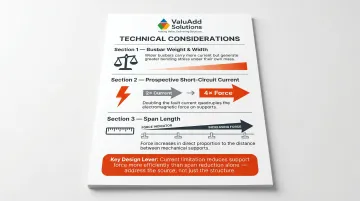
Three variables determine how hard the support system works:
- Busbar weight and width — heavier or wider busbars create more bending stress across the same span
- Prospective short-circuit current — electromagnetic force is proportional to the square of the peak current, so doubling fault current quadruples the force
- Span length — electromagnetic force increases directly with span length
Shorter spans mean stronger fault protection. Reducing span by 20% cuts mechanical stress by 20%, but reducing fault current by 20% reduces forces by roughly 36%—making current limitation the more powerful lever when both options are available.
Busbar support manufacturers typically provide load span tables for final design. ValuAdd's SB 7500 Busbar Support series, for example, includes published short-circuit withstand ratings and is tested to IEC 60865-1 for high-fault-current industrial installations.
Planning and Installing Your Busbar Support Spacing
Prerequisites and Safety Considerations
Before installation begins, confirm these critical parameters:
Required Information:
- System rated voltage and BIL (Basic Insulation Level)
- Prospective short-circuit current at the installation point
- Busbar material (copper or aluminum) and cross-section
- Enclosure pollution degree and IP rating
- Whether busbars will be bare or insulated
Each parameter directly feeds into clearance and support interval selection.
Non-Negotiables — Do NOT Proceed If:
- The insulator voltage class is lower than the system voltage
- Enclosure dimensions do not permit minimum NEC/IEC clearances
- The short-circuit rating of support insulators is lower than the system's prospective fault current
Undersized insulators can shatter under fault conditions, causing arc flash events and complete system failure.
How to Determine and Install Busbar Support Spacing (Step-by-Step)
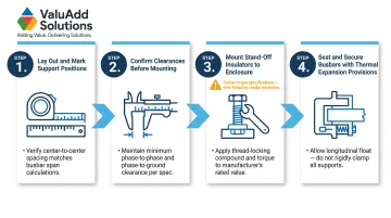
Step 1 — Lay Out the Busbar Run and Mark Support Positions
Starting from fixed termination points, mark insulator positions at the calculated interval. Begin at no more than half the interval distance from each end to prevent cantilever stress.
Critical Rules:
- Ensure no unsupported span exceeds the calculated maximum
- Corner bends and connection points always require an additional support
- Document the layout including clearance measurements for future maintenance reference
Step 2 — Confirm Clearances Before Mounting Insulators
Physically verify that planned insulator positions will maintain required phase-to-phase and phase-to-ground air clearances at all points, including at the narrowest cross-section of the enclosure.
Verification Process:
- Use a clearance gauge or template
- Document measurements against applicable standard values (NEC Table 408.56 or IEC 60664-1)
- Check clearances at the insulator mounting point—insufficient stand-off height is a common error
ValuAdd's technical team can assist in matching stand-off insulator height to clearance requirements for specific enclosure configurations.
Step 3 — Mount Stand-Off Insulators to the Enclosure Structure
Secure insulators to the mounting rail or back panel using the manufacturer's specified fastener type and torque value.
Critical Torque Guidelines:
- Under-torqued fasteners allow vibration-induced loosening
- Over-torqued fasteners crack BMC/epoxy insulator bodies
- Always use a calibrated torque wrench
Match insulator mounting hole spacing to the busbar center-to-center phase distance. ValuAdd's SB P 30 Busbar Support series is optimized for switchboard applications with configurations for 3-pole and 4-pole systems.
Step 4 — Seat and Secure Busbars Into Supports
Lay busbars into the insulator clamps, confirm phase orientation and labeling, then tighten clamping hardware to the specified torque.
Thermal Expansion Considerations:
- Busbars must be free to expand thermally
- Clamps should retain the bar without rigid pinching
- Bolted connection joints should include expansion provisions per IEC 60947-1
Post-Installation Checks and Validation
Required Checks Before Energization
Clearance Re-Measurement:
- Re-measure all phase-to-phase and phase-to-ground clearances with a calibrated gauge
- Compare to NEC/IEC reference values
- Document any deviations
Torque Audit:
- Verify all insulator mounting and busbar clamping fasteners
- Use a torque wrench set to manufacturer specifications
- Re-tighten any fasteners that have loosened during installation
Visual Inspection:
- Confirm no insulator is cracked, chipped, or misaligned
- Check for foreign objects or debris that could reduce clearances
- Verify busbar seating in all support clamps
Once physical checks pass, complete electrical validation before energizing.
Functional Validation: Dielectric Testing
Conduct a high-potential (hipot) or insulation resistance test between phases and phase-to-ground to confirm stand-off insulators provide adequate dielectric isolation.
IEC 61439-1 Dielectric Test Voltages:
| Rated Insulation Voltage (Ui) | AC Test Voltage (r.m.s.) | DC Test Voltage |
|---|---|---|
| 300 < Ui ≤ 690 V | 1,890 V | 2,670 V |
| 690 < Ui ≤ 800 V | 2,000 V | 2,830 V |
Test duration is typically 1 second for routine verification. Skipping this step leaves latent insulation faults undetected. Those faults will surface under live operating conditions, where the consequences include arc flash injuries and equipment destruction.
Common Busbar Support Spacing Mistakes and How to Fix Them
Three installation errors account for most busbar support failures: oversized support intervals, mismatched insulator voltage ratings, and inadequate phase-to-ground clearance. Each has a specific, correctable cause.
Excessive Support Interval Spacing
Problem: Supports are placed farther apart than the calculated maximum, leaving long unsupported busbar spans.
Likely Cause: Following a "rule of thumb" interval (such as "always use 500mm") without accounting for the system's actual prospective short-circuit current or the busbar's cross-section weight.
Fix:
- Recalculate the maximum permissible span using the busbar manufacturer's load span data and the installation's verified fault current
- Add intermediate support insulators to bring all spans within the calculated limit
- In one installation, reducing support spacing from 500mm to 350mm reduced calculated deflection from 64mm to under 15mm
Wrong Insulator Voltage Class
Problem: Stand-off insulators rated below the system voltage are installed, causing insulation breakdown or flashover under normal operating or transient overvoltage conditions.
Likely Cause: Selecting insulators by physical fit or phase spacing only, without verifying the voltage class stamped on the insulator against the system's rated and impulse voltages.
Fix:
- Replace with insulators rated at or above the system's BIL
- Confirm that a 690V-rated insulator meets BIL requirements — a higher test voltage may still apply even at that system voltage
- Verify both Ui (for creepage) and Uimp (for clearance); a 400V system in Overvoltage Category III, for example, requires Uimp = 4kV
ValuAdd's Female-Female Hexagonal Insulators cover the full range from 500 VAC/DC to 2400 VAC/DC, so selecting the correct voltage class for both low-voltage and medium-voltage installations doesn't require sourcing from multiple suppliers.
Insufficient Phase-to-Ground Clearance at the Insulator Mount
Problem: The insulator positions the busbar too close to the grounded enclosure backplate or rail, violating minimum clearance requirements.
Likely Cause: Using a stand-off insulator with insufficient height (creepage height) for the voltage class and pollution degree, or mounting to a rail that reduces the effective air gap.
Fix:
- Replace with a taller stand-off insulator that achieves the required clearance
- Or reposition the mounting rail to restore proper clearance
- Verify clearance at the narrowest point, not just at the insulator body
When enclosure geometry makes clearance verification less straightforward, ValuAdd's technical team can help match insulator height to specific configurations and confirm compliance with NEC and IEC requirements.
Pro Tips for Getting Busbar Support Spacing Right
Always establish support positions on paper (or in a CAD layout) before ordering insulators. Spacing errors found after components arrive typically mean reordering — phase center distances are not interchangeable between insulator series. Document the final layout including clearance measurements as part of the panel build record for future maintenance reference. ValuAdd provides CAD files and technical documentation for their busbar support products to support this planning process.
In high-vibration environments (motors, compressors, pumps common in manufacturing and processing plants), reduce support intervals by 20–30% below the calculated maximum and specify insulators with higher mechanical load ratings. Vibration-induced micro-movement at insufficiently supported busbars causes fretting corrosion at clamp contact points over time.
Fretting strips protective plating — gold, silver, tin — exposing base metals to oxidation. That drives up electrical resistance, creating localized heating and eventual joint failure. Address this with:
- Belleville (disc spring) washers or wedge-locking washers to maintain contact force
- Flexible copper braids across expansion joints to decouple vibration sources
- Strict torque control and periodic thermographic inspections
ValuAdd's Ultraflexx® highly flexible busbars feature press-welded connections across the entire cross-section, providing vibration-resistant performance specifically designed for these demanding applications.
Know when to engage a specialist. If the prospective short-circuit current at the installation point exceeds the tested parameters of standard insulator span tables, or if the installation involves medium voltage, the support spacing calculation should be reviewed by a qualified electrical engineer before installation proceeds. IEC/TR 61641 defines the threshold above which additional analysis is required.
Frequently Asked Questions
What is the minimum spacing between busbars?
Minimum phase-to-phase spacing depends on voltage level and whether busbars are insulated or bare. For bare busbars in a 250V system, NEC Table 408.56 requires 31.8mm same-surface clearance. For 400V systems under IEC 60664-1, minimum clearance is 3.0mm (assuming Overvoltage Category III), but creepage distance for Pollution Degree 2 is 2.0mm.
What is the minimum clearance to the bottom of a bus enclosure where the busbars are uninsulated?
Under NEC 408.56's "live parts to ground" column, uninsulated bare busbars in systems up to 600V require a minimum 25.4mm (1 inch) clearance from any grounded metal surface, including the enclosure bottom. The commonly cited ≥20mm figure for low-voltage bare copper is a manufacturer-specific guideline, not a universal code minimum.
What is the clearance for a 400V busbar?
For 400V systems under IEC 60664-1 (Pollution Degree 2, Overvoltage Category III), the minimum air clearance is 3.0mm with a 2.0mm creepage distance for Material Group II insulators. Higher pollution degrees or lower-CTI materials require greater values — consult the standard's tables directly for those conditions.
What are busbar supports?
Busbar supports are insulating mechanical components that secure busbars within an enclosure, maintain required phase-to-phase and phase-to-ground clearances, and resist electromagnetic forces during fault conditions. Common materials include BMC, SMC, epoxy resin, and ceramic — all selected for high dielectric strength.
How far apart should busbar support insulators be spaced?
General industry guidance is 300mm–500mm for standard low-voltage industrial busbars. However, the exact interval depends on busbar cross-section, weight, and prospective short-circuit current. High-current installations or high-vibration environments require shorter, reinforced intervals—often 200mm–350mm.
What happens if busbar supports are spaced too far apart?
Excessive spacing leaves busbars vulnerable to deflection under their own weight and violent displacement under short-circuit electromagnetic forces. The result can be busbar contact, insulator fracture, arc flash, and full system failure — in one documented case, inadequate spacing under ~4,400 N of fault force caused over 64mm of deflection.