Introduction
In industrial control panels, motor control centers, and processing equipment, power distribution blocks are how you get clean, organized power routing without wire splicing. Installed downstream of circuit breakers or disconnect switches, they distribute power from a single source to multiple circuits — but only when wired correctly.
Poor wiring practices are the leading cause of system failures in industrial environments. Wrong wire gauge selection, improper torque application, skipped ferrules, and missing certifications all contribute to overheating, voltage drop, and costly downtime.
The stakes are concrete: nearly half (46%) of non-home fires caused by electrical failure involve arcing, according to NFPA data, with loose connections a specifically tracked ignition factor. This guide covers the wiring practices that prevent those failures.
Key Takeaways
- Use power distribution blocks to split one main conductor into multiple branch circuits without splicing
- De-energize upstream circuits and verify zero voltage before starting any wiring work
- Match wire gauges to the block's rated capacity — never exceed the maximum conductor size
- Apply ferrules on stranded wire and torque all terminals to manufacturer specifications
- Install blocks downstream of correctly rated circuit breakers or fuses
What You Need Before Wiring a Power Distribution Block
Preparation determines connection quality and long-term reliability. Rushing it leads to rework — and in industrial panels, that's expensive.
Equipment and Block Specifications
Confirm the block's current rating (amperage) and voltage rating match your system requirements. ValuAdd carries Socomec power distribution blocks rated from 90A to 255A for single-pole applications and 125A to 175A for three-pole configurations, all rated for 690 VAC systems.
Verify the block carries appropriate certifications for your application:
- UL 1953 and UL 1059 for North American installations
- CE Certified and IEC 61439-1/IEC 60947-7-1 for international compliance
- IP-rated enclosures (IP65, IP66, or IP68) for harsh industrial or wet environments
Check the block supports your required number of output circuits and accepts the input/output conductor sizes specified in your panel design. Socomec blocks accommodate 7–8 conductors per pole depending on the model. They support standard solid, stranded, and fine wire strands.
Tools, Materials, and Conductor Readiness
Required tools:
- Insulated screwdrivers with proper blade width for terminal screws
- Calibrated torque screwdriver or torque wrench
- Wire strippers rated for your conductor gauge
- Ferrule crimping tool (for stranded conductors)
- Multimeter (calibrated for voltage and continuity testing)
- Appropriate PPE (insulated gloves, safety glasses, arc-rated clothing)
Material requirements:
- Correctly gauged wire matching terminal AWG range
- Wire ferrules for all stranded conductors
- Heat shrink tubing for additional insulation protection
- Terminal labels or wire tags for circuit identification
Safety and Compliance Checks
Establishing an Electrically Safe Work Condition is mandatory before any termination work. OSHA 29 CFR 1910.147 requires employers to establish formal energy control programs. This includes documented procedures, dedicated lockout/tagout (LOTO) hardware, and annual program inspections.
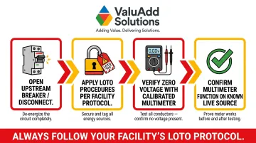
Before touching any terminals:
- Open the upstream circuit breaker or disconnect switch
- Apply LOTO procedures per facility protocol
- Use a calibrated multimeter to verify zero voltage at the installation point
- Test the multimeter on a known live source to confirm it's functioning properly
How to Connect a Power Distribution Block: Step-by-Step
Step 1: Mount the Block and Prepare the Installation Point
Select the correct mounting method based on your enclosure layout. ValuAdd's Socomec distribution blocks support both DIN rail and direct panel mounting, accommodating most enclosure configurations without adapter hardware.
Ensure the block seats firmly with no play. Vibration in industrial environments will loosen a poorly mounted block over time. Confirm adequate clearance around the block for wiring access and airflow — crowded installations trap heat and accelerate insulation degradation.
Before touching any terminals, verify the upstream disconnect or breaker is open and locked out. Test the connection point with a calibrated multimeter to confirm zero potential.
Step 2: Prepare the Conductors
Strip each conductor to the strip length specified in the manufacturer's datasheet. Too short reduces contact area and connection integrity; too long leaves exposed conductor outside the terminal, creating shock and short-circuit risk.
For stranded wire, crimp a correctly sized wire ferrule onto the stripped end before insertion. This consolidates strand bundles, prevents individual strands from splaying into adjacent terminals, and maintains contact pressure over time. Properly crimped ferrules are required by IEC 60947 standards for stranded conductors in screw-type terminals.
For solid conductors, inspect the stripped end for nicks or damage from the stripping tool. A damaged conductor reduces cross-section and can fail at rated load.
Step 3: Connect the Input and Output Conductors
Insert the main (input) conductor into the designated line-side terminal first. Confirm the conductor is fully seated by giving it a gentle tug after initial insertion — partial seating is a leading cause of high-resistance joints.
Connect each output (load-side) conductor to its assigned terminal, working methodically from one end of the block to the other. This systematic approach prevents skipping terminals or double-terminating a port.
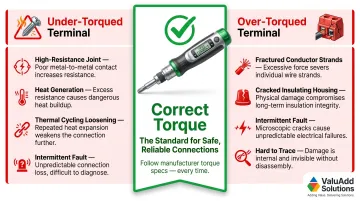
Once all conductors are seated, torque every terminal screw to the manufacturer's specified value using a calibrated torque tool. NEC 2023 Section 110.14(D) mandates that tightening torque must match the equipment markings or installation instructions — no exceptions.
- Under-torquing leaves a high-resistance connection that generates heat at the joint
- Over-torquing can crack the insulating housing or damage conductor strands
Label each output circuit at the terminal immediately after connection using adhesive markers or wire tags. In multi-circuit panels, unlabeled distribution blocks create dangerous confusion during maintenance and troubleshooting.
Step 4: Test and Verify the Installation
Perform a visual inspection before energizing:
- Confirm no bare conductor is exposed outside any terminal
- Verify all screws are flush and not cross-threaded
- Check that no wire insulation is pinched or kinked at terminal entry
With the upstream circuit still de-energized, use a multimeter in continuity mode to verify each output terminal has a solid connection back to the input.
Re-energize the circuit through the upstream breaker or disconnect. Measure voltage at each output terminal with a calibrated multimeter — all outputs should read within acceptable tolerance of the input voltage. Note any terminals showing significant deviation for immediate re-inspection.
Key Wiring Parameters That Affect Connection Quality
Even a correctly installed block will underperform or fail prematurely if these variables are not properly controlled during wiring.
Conductor Size (AWG) vs. Terminal Capacity
Each terminal is engineered for a specific conductor cross-section range. Wire that's too small for the terminal leaves gaps around the conductor — increasing resistance and allowing the wire to pull out under vibration. Each terminal is engineered for a specific conductor cross-section range. Wire that's too small leaves gaps around the conductor, increasing resistance and allowing pull-out under vibration.
Undersized conductors cause localized heating at the terminal, can exceed the wire's ampacity rating per NEC Table 310.16, and may trigger nuisance tripping of upstream overcurrent devices.
Terminal Torque Value
Torque directly controls contact force between the screw clamp and the conductor — and both insufficient and excessive torque are failure modes. Always follow the manufacturer's torque specification (typically listed in N·m or in·lb) for your exact block model.
Under-torqued terminals develop resistance over time as thermal cycling loosens the connection. Over-torqued terminals can fracture conductor strands or crack the housing, producing an intermittent fault that's hard to trace without re-examining every terminal in the circuit.
Block Current and Voltage Rating vs. System Load
The block's rated amperage must equal or exceed the total combined load of all output circuits, and voltage rating must cover the system operating voltage — including transient spikes. These aren't conservative suggestions; they're the floor.
UL 1059 testing permits a maximum temperature rise of 30 K at 25°C ambient. Running a distribution block near or above its rating accelerates insulation degradation and increases fire risk — a concern that compounds quickly inside hot industrial control panels.
Conductor Preparation Method (Ferrule vs. Bare Stranded)
Bare stranded wire in a screw terminal is a long-term liability. Individual strands can migrate outside the terminal from vibration and thermal cycling, creating short-circuit risk with adjacent terminals.
Properly crimped ferrules maintain a uniform contact cross-section throughout the installation's service life. Many industrial standards — including IEC 60947-7-1 — require ferrules for stranded conductors in screw-type terminals.
Common Wiring Mistakes to Avoid
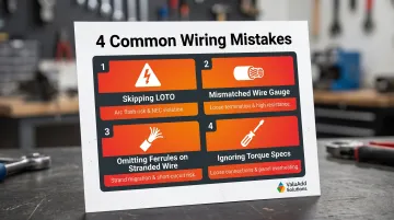
Skipping de-energization and LOTO: Attempting to wire or re-terminate a distribution block under live conditions is both an NEC violation and the leading cause of arc flash incidents in panel work. In fiscal year 2024, OSHA issued 2,443 citations for violations of the Control of Hazardous Energy standard. No time savings justify this risk.
Mismatching wire gauge to terminal rating: Installing a conductor smaller than the terminal's minimum rated size (often done to "make it fit") creates a loose termination with high contact resistance. Always select wire gauges from within the block's published conductor acceptance range.
Omitting ferrules on stranded conductors: Bare stranded wire in screw terminals can splay during tightening, with stray strands bridging to adjacent terminals. Use correctly sized ferrules on all stranded conductors to prevent this failure mode.
Ignoring torque specifications: Finger-tightening or using an uncalibrated screwdriver introduces inconsistency across terminals. Loose connections are a leading cause of electrical panel failures in industrial facilities. According to a Fluke infrared guide, thermal imaging studies flag temperature differences exceeding 15°C versus similar components as a major discrepancy requiring immediate repair.
Troubleshooting Power Distribution Block Wiring Issues
Even properly installed blocks can develop issues due to thermal cycling, vibration, or load changes over the life of a system. Early diagnosis prevents escalation to equipment damage.
Overheating at the Block or Discoloration of Insulation
A loose terminal connection — under-torqued or worked loose over time — creates a high-resistance joint that converts electrical energy to heat. A block drawing current above its rating will overheat uniformly across all terminals, which helps distinguish overload from a single bad connection.
To diagnose and correct:
- De-energize the circuit and re-inspect all terminal torque values with a calibrated torque screwdriver
- Check conductor size against rated capacity
- Verify total output load does not exceed the block's ampere rating
- Replace the block immediately if the housing shows visible melting or cracking
Voltage Drop Across Output Terminals
Poor contact at the terminal, undersized output conductors, or a corroded connection point reduces effective cross-section and increases resistance. The result is measurable voltage loss that affects downstream equipment performance.
Measure voltage at the input terminal and at each output terminal individually. NEC recommends maximum 3% voltage drop on branch circuits and 5% total combined drop. A drop exceeding that threshold at one specific output points to a bad connection at that terminal — re-strip the conductor, inspect for corrosion or strand damage, install a new ferrule, and re-torque.
Terminal Screw That Won't Achieve Proper Torque or Turns Freely
Over-torquing or cross-threading strips the screw threads and prevents the clamp from generating adequate contact force. Using the wrong screwdriver blade width is a frequent cause — it damages the screw head and allows slippage before full torque is reached.
A terminal with a stripped or damaged screw cannot be field-repaired reliably. The block must be replaced. Using manufacturer-specified screwdriver tip sizes from the start is the only reliable way to prevent this failure mode.
Frequently Asked Questions
How does a power distribution block work?
A power distribution block accepts a single large input conductor from the main power source and routes that power to multiple smaller output conductors on a shared bus. This eliminates wire splicing and provides organized, serviceable termination points.
Do I need a distribution block for 2 amps?
For a 2-amp load, a distribution block is generally not necessary — a simple terminal block or direct connection is sufficient. Distribution blocks make the most sense when you need to branch a single feed into three or more circuits within a panel or enclosure.
What wire gauge should I use with a power distribution block?
Wire gauge must fall within the conductor acceptance range specified by the block manufacturer (printed on the product or datasheet) and must be sized to safely carry the anticipated load current per NEC ampacity tables. Never use wire smaller than the minimum terminal-rated conductor size.
What is the difference between a power distribution block and a terminal block?
A power distribution block accepts one large-gauge input conductor and branches it to multiple smaller-gauge outputs on a shared bus. A terminal block, by contrast, connects wires of similar gauge for circuit continuation or signal routing. Distribution blocks handle higher currents and conductor size transitions.
Do power distribution blocks need to be fused?
The distribution block itself is not a protective device — it must be installed downstream of an appropriately rated circuit breaker or fuse. NEC Section 240.21 establishes that overcurrent protective devices must be placed at the point where conductors receive their supply. Each output branch may require its own overcurrent protection depending on conductor size and NEC branch circuit requirements.
What torque should I use when tightening power distribution block terminals?
The correct torque value is specified by the block manufacturer in the product datasheet (typically in N·m or in·lb) and varies by terminal size. Always use a calibrated torque screwdriver set to that value — both under- and over-torquing cause connection failures over the equipment's service life.