
Introduction
Choosing the wrong busbar size leads to overheating, unexpected downtime, and costly failures—challenges familiar to plant engineers and system integrators working with high-demand industrial loads. In sectors like automotive manufacturing, where unplanned downtime costs an average of $2.3 million per hour, a thermal failure caused by an undersized busbar hits fast and hard.
This guide walks through how to size copper and aluminum busbars using formulas, key parameters, and standard sizing references. It covers applications from water treatment switchgear and oil and gas power distribution to motor control panels in manufacturing—so you can select the right busbar with confidence.
If you're specifying busbars for a critical industrial system, start here.
TLDR: Busbar Sizing at a Glance
- Cross-sectional area (mm²) is the foundation — divide required current by the material's current density
- Copper carries ~1.2 A/mm² and aluminum ~0.8 A/mm² under standard conditions
- Apply a 25% safety factor on top of your calculated load current
- Derating reduces usable ampacity — ambient temperature, grouping, and ventilation can cut it by 20–50%
- Short-circuit sizing uses A = √(I² × t) / k — where k = 205 (copper) or 126 (aluminum)
What Is a Busbar and Why Does Sizing Matter?
A busbar is a conductive metallic bar or strip used to distribute electrical power inside switchgear, panel boards, and busways. It serves as a central node that accepts current from incoming feeders and distributes it to multiple outgoing circuits — a rigid, high-current alternative to cable wiring.
Sizing directly affects both safety and cost. Get it wrong in either direction and you pay for it:
- Undersized busbars overheat, produce voltage drops, and create arc flash and fire risks
- Oversized busbars drive up material and installation costs without adding performance
- Either error can trigger compliance failures in systems requiring UL or NEC conformance
The stakes are real: according to ARC Advisory Group, downtime costs process industries $1 trillion annually. Undersized busbars feed directly into that figure — insulation degradation, arc flash events, and unplanned outages all trace back to thermal overload from conductors that can't handle the load.
Key Parameters That Affect Busbar Sizing
Current-Carrying Capacity (Ampacity)
The busbar must handle the total continuous load plus a safety margin. Standard practice requires 125% of the maximum continuous current to account for load variations and protect against overheating.
Current Density
Current density is the ratio of current per unit cross-sectional area (A/mm²). This value differs by material and drives the cross-sectional area calculation:
- Copper: ~1.2 A/mm²
- Aluminum: ~0.8 A/mm²
- Silver: ~1.6 A/mm² (reference only)
These are heuristics for initial sizing. IEC 61439-1 does not mandate fixed current density values; instead, it enforces strict temperature-rise limits based on installation conditions.
Cross-Sectional Area
Cross-sectional area (width × thickness in mm) is the physical outcome of the current density calculation. Standard busbars come in defined dimension pairs such as 40×10 mm, 63×10 mm, and 100×10 mm. Match your calculated area to the nearest standard size that meets or exceeds your requirement.
Ambient Temperature and Installation Environment
Higher ambient temperatures reduce a busbar's ability to dissipate heat, which means a larger cross-section or derating is required. IEC 61439-1 references a 35°C daily average ambient with a 40°C peak, and permits up to a 30°C rise at the busbar surface depending on the component and material type.
Harmonic Currents in Industrial Systems
When busbars connect to VFDs, soft starters, or motor control panels — common in manufacturing, water treatment, and oil and gas — harmonic currents add thermal load that standard nameplate current ratings don't capture.
IEEE 519-2014 establishes Total Demand Distortion (TDD) limits at the Point of Common Coupling (PCC). Non-linear loads distort current waveforms, so the true RMS current becomes:
I_rms = √(I₁² + I₂² + I₃² + ... + Iₙ²)
Because power loss equals I²R, even moderate harmonic distortion increases thermal stress. Key implications for busbar sizing include:
- Higher true RMS current than the nameplate load suggests, requiring a larger cross-section
- Elevated thermal stress on insulation and connection points
- Neutral busbars in high triplen harmonic systems (3rd, 6th, 9th, 12th...) often require oversizing to 150–200% of the phase conductors
If your system includes significant non-linear loads, harmonic analysis should be completed before finalizing busbar dimensions — not after installation.
How to Calculate Busbar Size: Step by Step
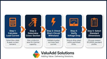
Before diving into each step, here's the overall process at a glance:
- Calculate total load current and apply a 1.25 safety factor
- Divide design current by allowable current density to get minimum cross-section
- Check short-circuit withstand capacity using the thermal stress formula
- Verify voltage drop stays within permissible limits
- Select the nearest standard dimension and apply derating factors
Determine Total Load Current
Step 1: Calculate the total load current in amperes by summing all connected loads.
For three-phase systems: I = P / (√3 × V × PF)
For single-phase systems: I = P / (V × PF)
Use the maximum continuous current, not just the rated load.
Apply the safety factor: Multiply the calculated load current by 1.25 (25% safety margin) to get the design current.
Example:
- Three-phase load: 150 kW at 480V, PF = 0.9
- I = 150,000 / (√3 × 480 × 0.9) = 200 A
- Design current = 200 × 1.25 = 250 A
Calculate Required Cross-Sectional Area
Step 2: Divide the design current by the allowable current density for the chosen material to get the minimum required cross-sectional area in mm².
Formula: A (mm²) = Design Current (A) / Current Density (A/mm²)
Example for copper busbar (250 A): A = 250 / 1.2 = 208 mm²
Example for aluminum busbar (250 A): A = 250 / 0.8 = 313 mm²
Aluminum requires 1.5× the cross-section of copper for the same load — a key tradeoff against aluminum's lower cost and weight.
Check Short-Circuit Withstand Capacity
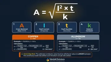
Step 3: Verify the busbar can withstand fault conditions using the thermal stress formula.
Formula: A = √(I² × t) / k
Where:
- A = cross-sectional area (mm²)
- I = fault current (amperes)
- t = fault duration (seconds, typically 0.1 to 1.0 s)
- k = material constant
Material constants:
- Copper: k = 205
- Aluminum: k = 126
The busbar must satisfy whichever of the two calculated areas (continuous load or short-circuit) is larger.
Example:
- Fault current: 25,000 A
- Fault duration: 0.5 seconds
- Copper: A = √(25,000² × 0.5) / 205 = 86 mm²
- Since 208 mm² > 86 mm², the continuous load governs
Verify Voltage Drop
Step 4: Calculate expected voltage drop using:
V_drop = I × R × L
Where R is the resistivity of the busbar material per unit length.
Voltage drop must remain within permissible limits — typically under 1–2% for busbars in power distribution. NEC (NFPA 70) doesn't set a hard voltage drop limit, but industry practice — consistent with IEC 60364-5-52 — targets no more than 3% for lighting circuits and 5% for power circuits measured from the source.
Longer runs or high-resistance materials may require upsizing the cross-section to maintain acceptable voltage drop.
Select Standard Dimensions and Validate
Step 5: Select the nearest standard busbar dimension (width × thickness) that meets or exceeds the calculated area.
For the 208 mm² copper example:
- 30×10 mm = 300 mm² ✓
- 25×10 mm = 250 mm² ✓ (minimal margin)
- 20×10 mm = 200 mm² ✗ (too small)
Choose 25×10 mm or 30×10 mm depending on derating factors and available standards.
Before locking in the final size, apply derating factors for ambient temperature, enclosure type, and bundled conductors — these can reduce rated ampacity by 20–40% in typical industrial installations.
Copper vs. Aluminum Busbars: Sizing Differences Compared
Electrical Conductivity
Copper offers 100% IACS conductivity, while aluminum 1350-H19 provides 61% IACS. In practical terms, an aluminum busbar needs approximately 1.5× the cross-sectional area of an equivalent copper busbar to carry the same current — a direct impact on panel layout and conduit sizing.
Weight and Cost
Aluminum has a density of 2.70 g/cm³ compared to copper's 8.91 g/cm³—approximately one-third the weight. Aluminum is generally lower in material cost, making it attractive for long-run or overhead installations where weight matters. Copper's higher upfront cost makes more sense in space-constrained switchgear where a smaller busbar cross-section justifies the premium.
Mechanical and Thermal Behavior
Beyond size and cost, material behavior during installation and operation differs significantly between the two:
- Thermal expansion: Copper expands at 17×10⁻⁶/°K vs. aluminum's 23×10⁻⁶/°K, making copper the better choice in high-vibration or high-temperature environments
- Bend radius: Aluminum requires a minimum bend radius of twice its thickness; copper can be bent to a radius equal to its thickness
- Oxidation: Aluminum is more susceptible to oxidation at contact joints — anti-oxidant compound and compatible hardware are required
- Mechanical strength: Copper handles higher mechanical stress, relevant in dense panel assemblies with frequent bus connections
Comparison Summary
| Property | Copper | Aluminum | Best Fit |
|---|---|---|---|
| Current Density | 1.2 A/mm² | 0.8 A/mm² | Copper for high-density panels |
| Relative Area | 1.0× | 1.5× | Aluminum requires more space |
| Weight | Heavy | ~30% of copper | Aluminum for long runs |
| Cost | Higher upfront | Lower material cost | Budget depends on application |
| Applications | Compact switchgear, high-current panels | Busways, substations, overhead |

Standard Busbar Sizes, Derating Factors, and Common Mistakes
Standard Sizes
Common standard busbar dimensions for metric systems include:
- 20×6 mm, 20×10 mm, 30×10 mm, 40×10 mm, 63×10 mm, 80×10 mm, 100×10 mm
For North American DC telecom and power systems:
- 1/4″ × 1″ through 1/2″ × 8″
Always verify that the chosen size meets the calculated minimum cross-sectional area and relevant standards (IEC 61439, NEC, or ANSI as applicable).
Derating Factors
Three primary derating factors reduce usable ampacity:
1. Elevated Ambient Temperature At 50°C, a busway loses 10% of its rated capacity compared to the standard 40°C baseline, according to Eaton's Pow-R-Way III technical data.
Typical derating multipliers (40°C baseline):
| Ambient Temperature | Derating Multiplier |
|---|---|
| 40°C | 1.00 |
| 45°C | 0.95 |
| 50°C | 0.90 |
| 55°C | 0.85 |
| 60°C | 0.80 |
2. Multiple Busbars Stacked or Grouped Stacking multiple bars per phase reduces per-bar ampacity by 10–20% due to mutual heating and restricted convection.
3. Enclosed or Poorly Ventilated Installations Enclosed installations restrict airflow and heat dissipation compared to open-air mounting, requiring additional derating.
These three factors often apply simultaneously — always calculate their combined effect before finalizing a busbar size.

Common Sizing Mistakes
Avoid these errors:
- Skip the 1.25 safety factor and your busbar will run at its thermal limit under continuous load
- Overlook short-circuit withstand — the adiabatic formula exists for this reason; don't bypass it
- Apply current density rules without derating — ambient temperature, grouping, and enclosure each reduce real-world ampacity
- Swap aluminum for copper at the same size — aluminum needs roughly 1.5× the cross-sectional area to carry equivalent current
Frequently Asked Questions
What size busbar do I need?
Size is determined by total load current (with a 25% safety margin), material current density (1.2 A/mm² for copper, 0.8 A/mm² for aluminum), and applicable derating factors. Follow the calculation process in this guide to find the minimum cross-sectional area, then select the nearest standard dimension.
How many amps is a 40×10 busbar?
A 40×10 mm busbar has a cross-sectional area of 400 mm². Using standard current densities, it carries approximately 480 A for copper (400 × 1.2) and 320 A for aluminum (400 × 0.8) before derating. Actual ampacity depends on installation conditions; for reference, IEC-based ampacity tables show a single flat copper bar can carry 990 A at a 50 K temperature rise under ideal conditions.
What size is a 400 amp busbar?
For copper, a 400 A busbar requires a minimum cross-section of ~333 mm² (400 ÷ 1.2), achievable with a 40×10 mm bar. For aluminum, the required area is ~500 mm², achievable with a 50×10 mm or 63×10 mm bar. Always verify against ampacity tables and apply derating as needed.
What is the difference between copper and aluminum busbars for sizing purposes?
Copper requires a smaller cross-section for the same current due to higher conductivity. Aluminum needs roughly 1.5× the cross-sectional area but is lighter and costs less, making it the better fit for long runs and weight-sensitive installations where space isn't the primary constraint.
What is the formula for busbar current carrying capacity?
The formula is: I_ccc = Current Density (A/mm²) × Width (mm) × Thickness (mm). Standard current density values are copper: 1.2 A/mm², aluminum: 0.8 A/mm². This must be adjusted with derating factors for actual installation conditions such as ambient temperature, grouping, and enclosure type.
What derating factors affect busbar ampacity?
The three primary derating factors are ambient temperature above 40°C, reduced spacing or stacking of multiple busbars, and enclosed or restricted-airflow installation environments. Each factor reduces the usable ampacity below the theoretical rating and must be accounted for before finalizing busbar dimensions.
Have a busbar sizing question for your specific application? ValuAdd's technical team can assist with material selection, derating calculations, and specification for motor control panels, switchgear, and power distribution systems. Contact us to discuss your project requirements and review our UL Listed and CE Certified busbar solutions.