Introduction
Picture this: A municipal water treatment plant needs to seamlessly transfer pumping loads from the grid to a backup generator during a scheduled maintenance window. Or consider a conveyor system in a packaging facility that requires quick, reliable forward/reverse switching to clear jams. In both scenarios, plant engineers face the same challenge—manually controlling electrical loads with precision, reliability, and safety in demanding industrial environments.
Cam switches are the proven mechanical solution. Unlike relay logic or automated contactors that require auxiliary power and programmable controls, cam switches deliver fail-safe, manual switching through a simple rotary mechanism. They handle motor control functions (direction reversing, star-delta starting, speed selection) and changeover applications such as main-to-backup power transfer, all within a single rugged package designed for industrial duty.
This guide covers how cam switches work, which types suit motor control and changeover applications, and the critical selection criteria — current ratings, certifications, and environmental protection ratings — that engineers and system integrators must verify before specifying.
TLDR — Key Takeaways:
- Cam switches use profiled cam discs on a rotating shaft to actuate multiple electrical contacts in precise, repeatable sequences
- Industrial types include changeover (transfer), multi-pole, step (multi-position), and isolating cam switches
- Supports forward/reverse switching, star-delta starting, and multi-speed motor control
- Handles main-to-backup power transfer and load source selection in industrial control panels
- Verify AC-23A rating, IP65/IP66/NEMA 4X protection, UL 98 or UL 508 listing, and break-before-make contact sequences
What Is a Cam Switch and How Does It Work?
A cam switch is a rotary electrical switch that uses profiled cam discs mounted on a central shaft to open and close sets of electrical contacts in a defined sequence as the operator rotates the shaft. Unlike a simple on/off toggle switch, a cam switch controls multiple circuits or functions simultaneously through a single rotational action—making it ideal for complex motor control and power transfer applications.
Core Operating Principle
As the operator turns the handle or knob, each cam lobe either pushes contact bridges closed or releases them to open. Multiple cams stacked on the same shaft allow simultaneous switching of several poles—critical for three-phase motor circuits where all three phases must open or close together.
A mechanical detent mechanism locks the shaft into discrete positions (typically 30°, 45°, 60°, or 90° angles), ensuring contacts fully seat and preventing the switch from resting between states.
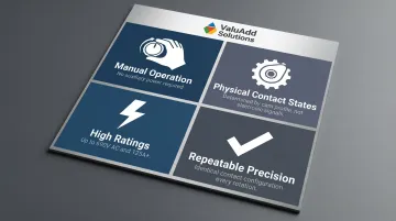
This purely mechanical design translates into practical advantages:
- Operates through manual rotation only, with no relay logic or auxiliary power required
- Contact states are physically determined by cam profiles, not electronic signals—eliminating dependence on control power
- Rated up to 690V AC and 125A, with heavy-duty models exceeding 315A for high-demand circuits
- Delivers the exact same contact configuration at each position, every time, with no drift or variation
In practice, this means a cam switch keeps working when PLCs fault, control power drops, or communication networks go down—conditions where electronic switching solutions can leave a circuit in an unknown state.
Types of Cam Switches for Motor Control and Changeover
Cam switches come in several configurations, each designed for specific switching functions. Choosing the right type depends on whether you're controlling a motor's direction, isolating a circuit for maintenance, or transferring between power sources.
Changeover Cam Switches
Changeover (also called transfer) cam switches route a load between two power sources—such as utility supply and a standby generator. The typical contact configuration follows a Source 1 / OFF / Source 2 sequence, where the intermediate OFF position is critical. This break-before-make design physically prevents both sources from being connected simultaneously, eliminating the risk of catastrophic source paralleling.
Common applications include:
- Municipal water treatment pumping stations
- Oil and gas facilities requiring manual power transfer during outages
- Manufacturing plants needing scheduled maintenance isolation
ValuAdd offers the COMO CS I-0-II Manual Cam Changeover Switch, available in I-II, I-0-II, and I-0-II with bypass configurations, with current ratings from 25A to 100A and compliance with IEC 60947-3 standards.
Multi-Pole Cam Switches
Multi-pole cam switches feature multiple poles (sets of contacts) switched simultaneously by a single shaft rotation. This is essential for three-phase motor circuits, where all three phases must open or close together to safely start, stop, or reverse a motor. A 3-pole or 4-pole cam switch ensures synchronized phase switching, preventing dangerous imbalances and equipment damage.
Common applications include:
- Three-phase motor control in conveyors, pumps, and compressors
Step (Multi-Position) Cam Switches
Step cam switches feature multiple switching positions, allowing sequential engagement of different circuit configurations. As the operator advances the switch through steps, different winding combinations or resistor stages are selected.
Common applications include:
- Multi-speed motor control such as fan speed adjustment and pump staging
- Star-delta motor starting sequences, transitioning from reduced-voltage start to full-voltage run
Selector / Isolator Cam Switches
Selector-type cam switches enable circuit selection—such as switching between Hand/Off/Auto control modes in industrial automation systems. Isolating cam switches serve as a means of safe electrical isolation during maintenance. Under OSHA 29 CFR 1910.147 (Lockout/Tagout), an "energy isolating device" must physically prevent the transmission of energy. Isolating cam switches meet this requirement when equipped with padlockable handles, allowing compliance with LOTO procedures.
Common applications include:
- Maintenance disconnects and LOTO-compliant safety isolation
- Mode selection (Hand/Off/Auto) in control panels
- Safety isolation in high-risk environments
Cam Switches in Motor Control: Key Switching Sequences
Cam switches are specifically designed to perform critical motor control functions in industrial settings. The three most common applications involve precise contact sequencing to safely control three-phase induction motors.
Forward/Reverse Motor Switching
A cam switch achieves forward/reverse control of a three-phase motor by physically swapping two of the three phase connections. The typical contact arrangement is a 3-position switch with positions labeled Forward / OFF / Reverse.
The intermediate OFF position is critical—it acts as a mechanical interlock, ensuring the motor is disconnected from power before the phases are reversed. This prevents phase shorting and severe mechanical stress that would occur if direction changed while the motor was still energized.
Applications: Conveyor systems (for clearing jams), hoists, machine tools, and process equipment requiring bidirectional operation.
Star-Delta (Wye-Delta) Starting
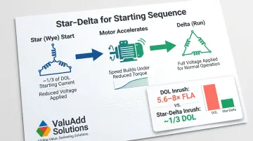
Direct-on-line (DOL) starting of large motors draws significant inrush current—typically 5.6 to 8 times the full-load current. This stresses the electrical system and can cause voltage sags affecting other equipment.
Star-delta starting reduces this impact. A multi-position cam switch first connects the motor windings in a star (wye) configuration, which reduces the phase voltage and drops the starting current to approximately 1/3 of DOL current. Once the motor accelerates, the operator manually turns the switch to the delta (run) position, applying full voltage for normal operation. Starting torque is also reduced to about 1/3 of DOL torque, making this method ideal for pumps, fans, and compressors—loads with low breakaway torque—but unsuitable for high-inertia or heavy-duty starting.
Applications: Larger motors (typically above 15 HP) in manufacturing plants, water treatment facilities, and HVAC systems where reducing electrical system stress is essential.
Multi-Speed Motor Control
For motors with multiple winding taps or pole-changing designs (Dahlander windings), a multi-position cam switch provides step-by-step speed control. As the operator advances through positions (e.g., 0-1-2), different winding configurations engage to alter motor speed.
This step-by-step contact engagement pattern enables gradual speed transitions, avoiding abrupt mechanical shock.
Applications: Fan speed control, pump staging (low/medium/high flow), and machine tool speed selection.
Safety Considerations in Motor Control Switching
The cam switch's mechanical interlock—created by the detent mechanism and cam profile—prevents simultaneous connection of incompatible circuit states. In a forward/reverse application, the switch physically cannot engage both directions at once.
Proper sizing is equally critical. Key requirements per IEC 60947-3 utilization categories:
- Rate for motor starting current, not just full-load running current
- AC-23A (motor duty) switches must make at 10× rated current and break at 8× rated current
- A 100A switch rated only for AC-21A (resistive loads) will fail if applied to a 100A motor circuit
- Specify padlockable handles to comply with OSHA lockout/tagout requirements
Cam Switches in Changeover Applications
Changeover applications involve transferring a load between two or more power sources without the risk of paralleling those sources. Cam switches provide a proven, reliable solution for manual changeover in industrial and infrastructure settings where automatic transfer switches are either unnecessary or undesirable.
Main Supply to Backup Generator Transfer
A common scenario: a water treatment pump station must transfer from utility power to a standby generator during a power outage or scheduled maintenance. A cam switch's Source 1 / OFF / Source 2 contact sequence ensures a break-before-make transfer, physically preventing both sources from being connected to the load simultaneously. This eliminates the risk of source paralleling, which can destroy generators, trip utility breakers, and cause catastrophic equipment damage.
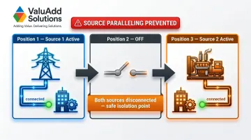
The detented OFF position also provides a safe isolation point during maintenance or troubleshooting.
Applications:
- Municipal water treatment facilities
- Oil and gas processing plants
- Wastewater pumping stations
- Manufacturing facilities with critical loads
Dual Power Supply Switching in Control Panels
In high-availability industrial applications, control panels may include multiple power feeds serving different sections of a machine or system. Cam switches provide the manual means to select the active feed, improving uptime and enabling flexible power management.
Applications:
- Redundant power feeds in automated manufacturing lines
- Process control systems
- Critical infrastructure installations
Load Circuit Selection and Circuit Isolation
Cam switches direct power to different load circuits or machines from a single supply point. This suits testing environments, process changeover scenarios, or sequential machine operation where only one load should be energized at a time.
They also serve as a visible, manual means of isolation prior to maintenance work. Unlike a standard disconnect switch, cam switches add the flexibility of multi-circuit control and padlock capability.
Applications:
- Test bench and lab environments requiring controlled load sequencing
- Process changeover stations in manufacturing
- Maintenance isolation points on multi-machine systems
Selecting the Right Cam Switch: Key Criteria and Certifications
Specifying the correct cam switch means matching electrical ratings, environmental protection, and certifications to what the application actually demands — here's the decision framework.
Electrical Ratings: Current, Voltage, and Utilization Category
Current Rating: Match the cam switch's rated current (in amperes) to the application's load. For motor loads, account for starting currents, which can be 5.6 to 8 times the full-load current. A motor with a 50A full-load rating may demand 400A during startup—requiring a switch rated for AC-23A motor duty, not just 50A continuous.
Voltage Rating: Industrial cam switches are typically rated up to 690V AC, with heavy-duty models reaching 1,000V AC. Verify the rating matches or exceeds the system voltage.
Utilization Category: This is the key spec that determines what type of load the switch can interrupt safely:
| Category | Load Type | Making Current | Breaking Current |
|---|---|---|---|
| AC-21A | Resistive loads (heaters, lighting) | 1.5 × Ie | 1.5 × Ie |
| AC-22A | Mixed resistive/inductive loads | 3 × Ie | 3 × Ie |
| AC-23A | Motor loads (highly inductive) | 10 × Ie | 8 × Ie |
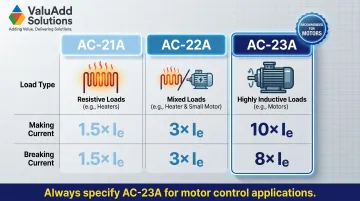
Always specify AC-23A for motor control applications. A switch rated only for AC-21A or AC-22A will not safely handle motor starting currents.
Poles, Positions, and Contact Configuration
Poles: The number of poles must match the electrical system:
- 2-pole: Single-phase motors or DC circuits
- 3-pole or 4-pole: Three-phase motors (4-pole includes neutral switching)
Positions: The number of positions must match the switching sequence:
- 3-position: Forward/Off/Reverse, or Source 1/Off/Source 2
- Multi-position: Star-delta starting, multi-speed control
Always cross-reference manufacturer contact configuration diagrams before finalizing a selection. These diagrams show the contact state at each switch position — confirming that phases are properly reversed or that the OFF position truly isolates all poles.
Environmental Protection and Build Quality
IP Ratings: IEC 60529 Ingress Protection (IP) ratings measure resistance to dust and water:
- IP65: Dust-tight and protected against low-pressure water jets — suitable for indoor industrial panels and outdoor enclosures
- IP66: Dust-tight and protected against powerful water jets — ideal for washdown environments and harsh outdoor installations
NEMA Ratings: NEMA 250 enclosure ratings are the North American standard:
- NEMA 4X: Provides protection against windblown dust, rain, hose-directed water, and corrosion (verified by 600-hour salt spray testing). The "X" designation is critical for marine, wastewater, and chemical processing applications.
Note: An IP66 rating does not equal NEMA 4X — IP standards do not test for corrosion resistance. For corrosive environments, verify NEMA 4X compliance explicitly.
Contact Materials: Silver alloy contacts offer superior conductivity and wear life compared to standard copper alloy. For high-cycle or high-current applications, specify switches with silver alloy contacts.
Certifications and Compliance Standards
In North America, the distinction between UL 508 and UL 98 is where most specification errors occur. Verify the following before finalizing any cam switch selection:
UL Listing:
- UL 508 (Industrial Control Equipment): Covers devices for starting, stopping, or protecting motors. A UL 508 switch can be used as a manual motor disconnect or supplemental circuit disconnect, but cannot be used as a branch circuit disconnect.
- UL 98 (Enclosed and Dead-Front Switches): Covers switches used as branch circuit, feeder, service, and motor circuit disconnecting means. If the cam switch serves as the primary branch or feeder disconnect, it must be UL 98 listed.
UL 98 switches require larger clearances and are built to withstand higher-energy fault events than UL 508-listed devices.
CE Marking: Required for equipment sold in the European Economic Area. CE marking indicates compliance with the Low Voltage Directive (LVD) 2014/35/EU and the Electromagnetic Compatibility (EMC) Directive 2014/30/EU. CE-certified cam switches meet harmonized standards like IEC/EN 60947-3.
Class E2 Clarification: "Class E2" is a load-break rating associated with medium/high-voltage switchgear under the IEC 62271 series. It is not a standard classification for low-voltage cam switches. For low-voltage applications, rely on AC-21/22/23 utilization categories.
ValuAdd's cam switches carry UL listing, CE certification, and IEC 60947-3 compliance — confirm the specific utilization category and disconnect rating required for your application before ordering.
Frequently Asked Questions
What is a cam switch?
A cam switch is a rotary electrical switch that uses profiled cam discs on a central shaft to open and close multiple electrical contacts in a defined sequence. Rotating the handle mechanically actuates contact bridges, allowing control of multiple circuits or motor functions with a single rotation.
What is the difference between a rotary switch and a cam switch?
All cam switches are rotary switches, but cam switches use profiled cam discs to actuate contacts in precise, engineered sequences. This lets them handle complex switching patterns, higher current loads (up to 125A or more), and multi-circuit control — well beyond the simpler, lower-current capability of standard rotary switches.
What are the different types of cam switches?
The main types include:
- Changeover (transfer) — switches loads between two power sources
- Multi-pole — simultaneously switches multiple phases in motor circuits
- Step (multi-position) — sequences circuit engagement for multi-speed or star-delta applications
- Selector — handles mode or circuit selection
- Isolating — provides safe electrical isolation with lockout/tagout capability
What current and voltage ratings are typical for industrial cam switches?
Industrial cam switches are commonly rated from 16A to 125A (with heavy-duty models exceeding 315A) and up to 690V AC. Engineers must also verify the utilization category (AC-21A, AC-22A, or AC-23A) to confirm the switch is rated for the specific load type—especially motor loads, which require AC-23A rating to handle starting currents.
How do cam switches compare to contactors for motor control?
Cam switches provide manual control suited for infrequent switching, maintenance isolation, and direction or speed selection. Contactors are electromagnetically operated for automated, high-frequency switching under PLC or relay control — rated for millions of cycles versus a cam switch's 100,000–500,000 operations. In practice, the two are often paired: a cam switch for local isolation and a contactor for automated process control.
What certifications should I look for when selecting a cam switch for a US industrial application?
UL listing is the primary requirement for North American installations — confirm whether your application calls for UL 508 (industrial control equipment) or UL 98 (branch circuit disconnect). The AC-23A utilization category confirms suitability for motor loads. For harsh environments, also verify IP65/IP66 or NEMA 4X enclosure ratings.
Ready to specify the right cam switch for your motor control or changeover application? Contact ValuAdd's technical team for product recommendations, datasheets, and application-specific guidance tailored to your facility's requirements.