Introduction
Picture this: A storm knocks out grid power to a manufacturing facility. The backup generator kicks on within seconds — but without the right connection, it can't safely deliver power to the building's circuits. Worse, it could back-feed live voltage onto utility lines where workers are making repairs.
That risk isn't hypothetical. The National Electrical Code (NEC Article 702) requires transfer equipment for standby systems precisely because uncontrolled switching between power sources creates serious hazards for both equipment and personnel. This is where a transfer switch becomes critical.
A transfer switch is the electrical device that connects your generator to a building's circuits while isolating the utility feed. It ensures power flows from exactly one source at a time — protecting equipment, personnel, and utility workers. What follows covers the main types, how each works, and how to choose the right one for your facility.
Key Takeaways
- Transfer switches safely route power between two sources — utility grid and backup generator — without allowing simultaneous connection
- They prevent dangerous back-feeding of electricity onto utility lines, protecting both workers and equipment
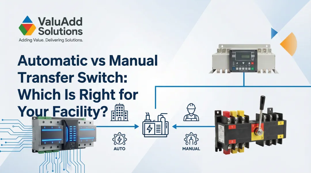
- Two primary types exist: manual transfer switches and automatic transfer switches (ATS), which detect outages and switch without human intervention
- ATS units are standard in industrial facilities where downtime directly impacts operations
- Industrial system costs vary widely by capacity, environment, and configuration; residential installs typically run $1,100–$3,000 as a baseline reference
- NEC requires transfer equipment for all permanent generator connections in commercial and industrial facilities
What Is a Transfer Switch?
A transfer switch is an electrical switch that transfers a building's electrical load between two power sources — most commonly from utility grid power to an emergency backup generator. It ensures only one source powers the building at any given time.
Transfer switches differ from circuit breakers in both function and design. Circuit breakers protect circuits by opening under overcurrent fault conditions. Transfer switches are designed to remain connected and route power under heavy loads; they do not provide overcurrent protection.
That distinction is reflected in their standards. Under UL 1008, transfer switches must carry a Withstand and Closing Rating (WCR), meaning they endure fault currents until upstream breakers trip. Circuit breakers (UL 489), by contrast, carry an Ampere Interrupting Capacity (AIC) rating that allows them to clear faults directly.
These technical distinctions carry legal weight as well. The National Electrical Code (NEC) Article 702.5 mandates transfer equipment for all fixed or portable optional standby systems. Temporary connections without transfer equipment are only permitted under strict exceptions involving qualified personnel and physical isolation. For commercial and industrial settings, this makes transfer switches not just useful but legally required.
How Does a Transfer Switch Work?
The transfer switch sits between the building's electrical panel and its two power sources. When active, it connects the load to exactly one source at a time. The switch physically breaks connection with one source before (or while) making connection with the other, so loads are never fed by two sources at once.
Automatic Transfer Switch (ATS) Operation
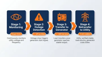
ATS units follow a precise control sequence:
- Monitoring: The ATS continuously monitors incoming voltage and frequency from the normal utility source.
- Outage Detection: When utility voltage drops below acceptable thresholds (confirmed by a 0–120 second time delay to avoid nuisance trips), the ATS sends a start signal to the generator.
- Transfer to Generator: Once the generator reaches stable voltage and frequency, the ATS transfers the load to the generator (with a programmable 0–1,800 second delay).
- Retransfer to Utility: When utility power is restored and verified as stable (typically after a 5-minute delay), the ATS retransfers the load back and signals the generator to shut down after a cool-down period (typically 5 minutes).
These time delays prevent unnecessary switching cycles that could damage sensitive equipment.
Preventing Back-Feeding
The control sequence above also serves a critical safety role: keeping the generator electrically isolated from the utility grid. Without that isolation, generator power can travel back onto utility lines. OSHA explicitly warns that connecting a generator directly to a building's electrical system without a transfer switch can energize wiring systems for great distances, creating severe electrocution risks for utility workers who assume lines are de-energized.
Load Management Capabilities
Transfer switches can be configured to power only critical circuits (lighting, HVAC, pumps) rather than an entire panel. More capable systems support load shedding and prioritization: generator capacity is directed to the most essential circuits first, with lower-priority loads dropped automatically. In fuel-constrained outages, this sequencing can mean the difference between a facility staying operational and a full shutdown.
Types of Transfer Switches
Manual Transfer Switches
Manual transfer switches require an operator to physically move the switch or flip individual circuit breakers to transfer load from utility to generator when an outage occurs. They are best suited for applications that can tolerate a brief power interruption and require a qualified person on-site. Manual switches are a cost-effective option for smaller installations where automatic operation isn't justified.
Common applications include:
- Small-scale commercial or light industrial facilities
- Small commercial buildings
- Applications with on-site personnel
Automatic Transfer Switches (ATS)
ATS units detect power failures, initiate generator startup, and complete the full transfer without human intervention. They are the standard choice for critical facilities where uptime cannot depend on manual response time.
Common applications include:
- Hospitals and healthcare facilities
- Data centers and telecom facilities
- Water treatment plants
- Industrial manufacturing operations
- Oil and gas processing facilities
Some systems offer remote-operated transfer switches as a middle ground: they require a qualified operator to initiate transfer but can be controlled via local or remote controls rather than hands-on mechanical operation. This is useful when direct physical access is impractical.
Open Transition vs. Closed Transition
Both manual and automatic switches can operate in either of the two primary switching modes below — each with distinct tradeoffs for load sensitivity and utility interconnection requirements.
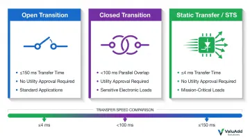
Open Transition (Break-Before-Make)
The switch breaks contact with the first source before connecting to the second, resulting in a brief intentional interruption (typically 150 milliseconds or less). This is the most common mode and prevents both sources from ever being live simultaneously. Suitable for most standard generator backup applications.
Advantages:
- No utility approval required
- Simpler design and lower cost
- Prevents accidental paralleling
Closed Transition (Make-Before-Break)
The switch momentarily connects both sources simultaneously (typically under 100 milliseconds) before fully transferring, resulting in zero interruption to loads. This requires both sources to be synchronized within tight tolerances:
- Voltage matching: ± 10% or less
- Frequency matching: 0.1 Hz slip or less
- Phase angle: ± 10° or less
Utility approval is required since the generator briefly runs in parallel with the grid. Ideal for sensitive electronic loads, data processing, and operations where even a fraction-of-a-second interruption triggers resets or data corruption.
Static Transfer Switches (STS)
Static transfer switches use solid-state power semiconductors (silicon-controlled rectifiers) instead of mechanical contacts, allowing transfer within a quarter of a power cycle (less than 4 milliseconds). With no moving parts, STS units provide faster, more reliable switching for ultra-sensitive loads.
Common applications include:
- Data centers with dual utility feeds
- Telecom facilities
- Mission-critical server environments
- Industrial processes requiring sub-cycle transfer times
| Transition Method | Switching Action | Typical Transfer Time | Utility Approval Needed? |
|---|---|---|---|
| Open Transition | Break-before-make | ≤ 150 milliseconds | No |
| Closed Transition | Make-before-break | < 100 ms overlap | Yes |
| Static Transfer (STS) | Solid-state SCR | ≤ 1/4 cycle (4 ms) | No |
Where Are Transfer Switches Used?
Industrial and Commercial Applications
Transfer switches are essential infrastructure across demanding industrial sectors:
- Manufacturing plants: Protect motors, control systems, and production lines from downtime
- Water treatment and wastewater facilities: Ensure pumps and treatment processes never lose power
- Oil and gas operations: Maintain critical instrumentation and safety systems
- Data centers: Protect servers from any interruption
- Hospitals and healthcare facilities: Power life support and medical equipment
- Commercial buildings: Maintain HVAC, lighting, security, and fire safety systems
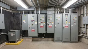
Industrial environments with harsh conditions — dust, moisture, corrosive atmospheres — require transfer switches in robust enclosures. NEMA Type 4X enclosures provide protection against water ingress, windblown dust, and corrosion, making them suitable for outdoor or chemical processing installations. Standard NEMA 3R enclosures work for most outdoor applications with protection against rain, sleet, and snow.
The U.S. has experienced 403 weather and climate disasters since 1980 with damages reaching or exceeding $1 billion each. As extreme weather events increase in frequency, reliable backup power infrastructure has become critical for business continuity and safety across all of these sectors.
Residential Applications
Residential installations use transfer switches to connect standby generators to specific hardwired circuits — furnaces, well pumps, sump pumps — that can't be served by extension cords. These applications follow the same isolation-and-switching principles as industrial systems, though at smaller scale and lower voltage ratings.
ValuAdd's Role in Industrial Installations
ValuAdd provides industrial electrical components engineered for demanding environments, including the certifications (UL Listed, NEMA Type 4X, IEEE 519 Compliant) that industrial-grade transfer switch installations require. System integrators and facility engineers specifying backup power infrastructure work with ValuAdd to identify the right disconnect switches, power distribution components, and enclosures for their specific environmental and safety requirements.
Transfer Switch vs. Interlock Device: What's the Difference?
An interlock device is a lower-cost alternative: a metal bracket installed on an existing circuit panel that prevents the main breaker and generator breaker from being switched on simultaneously. The generator outlet connects directly to the main panel rather than to a separate transfer switch subpanel.
Cost Comparison:
| Solution Type | Equipment Cost | Labor & Installation | Total Cost |
|---|---|---|---|
| Generator Interlock Kit | $200–$400 | $600–$1,000 | $900–$1,400 |
| Manual Transfer Switch | $400–$1,300 | $200–$1,500 | $1,100–$2,100 |
| Automatic Transfer Switch | $600–$2,500 | $500–$1,500 | $1,200–$3,000+ |
Those cost differences reflect real capability gaps. An interlock gives access to the full existing panel but lacks dedicated circuit management, automatic operation, and load prioritization. A transfer switch provides a safer, code-compliant solution with circuit selection and — for ATS — fully automatic operation. For commercial and industrial settings, an interlock device is generally not a code-compliant substitute for a proper transfer switch.
Don't Skip Either Device
Directly connecting a generator to a panel without either device is dangerous and illegal. The Consumer Product Safety Commission warns this practice creates severe electrocution risks to utility workers and neighbors served by the same utility transformer. It can also destroy equipment if utility power returns while the generator is still running.
Frequently Asked Questions
How much does it cost to put in a transfer switch for a generator?
Residential transfer switch installations typically range from $1,100 to $3,000 total, including equipment and licensed electrician labor. Industrial or high-capacity installations vary significantly based on system size, enclosure requirements (NEMA ratings), and installation complexity.
How does a transfer switch prevent backfeed?
The switch's break-before-make (or controlled make-before-break) mechanism ensures the generator is electrically isolated from the utility grid. This isolation prevents generator current from traveling back onto power lines where utility workers may be working, eliminating electrocution hazards.
Do I need a transfer switch for a generator?
For any permanent or hardwired generator connection, a transfer switch (or equivalent switching means) is required by the NEC in most jurisdictions. For portable generators used temporarily with extension cords, it isn't legally required — though plug-in connections without a transfer switch create backfeed risks and code compliance gaps.
Is a transfer switch worth it?
A transfer switch provides significant safety benefits: it prevents backfeeding, eliminates extension cord hazards, and enables powering of hardwired appliances. For commercial or industrial operators, it protects equipment and maintains uptime — more than half (54%) of data center outages cost over $100,000, with 16% exceeding $1 million.
Do you have to turn off the main breaker when using a transfer switch?
It depends on the switch type. Most transfer switches handle source isolation through their own controls, so a separate main breaker step isn't needed. Always follow the owner's manual or your electrician's instructions for your specific installation.