Introduction
Panel builders and system integrators face a familiar trio of challenges: cramped enclosures that demand every cubic inch of space, routing paths twisted around drives and transformers, and relentless pressure to cut build time without compromising electrical performance. The conductor you choose—cable, rigid bus, or flexible laminate—directly affects all three.
Flexible copper busbars address these constraints directly. Constructed from stacked layers of high-purity electrolytic copper enclosed in a PVC jacket, they bend, twist, and shape to fit where rigid bus can't—replacing multiple cable runs with a single lightweight conductor.
Key Takeaways:
- Stacked copper laminates in a PVC jacket eliminate crimped lugs and simplify terminations
- One busbar replaces multiple parallel cable runs, cutting installation time by up to 50%
- Rated 600 VAC / 750 VDC and 105°C — suitable for MCCs, VFD panels, and switchboards
- Sizing requires the NEC 125% continuous load rule plus appropriate temperature rise selection
- Installation requires strict compliance with bend radius, overlap, and torque specifications
What Are Flexible Copper Busbars?
Flexible copper busbars are multi-laminate conductors made from stacked layers of high-purity electrolytic copper foil enclosed in a protective PVC insulating jacket. Unlike rigid copper bus or stranded cable, the individual laminate layers slide against each other — enabling the busbar to be bent, twisted, and shaped without damaging the conductor or reducing electrical performance.
Construction Elements
The core is fabricated from Electrolytic Tough Pitch (ETP) copper — UNS C11000 (CDA 110) — with a minimum purity of 99.90% including silver. Copper foil and strip meet ASTM B152/B187 standards.
Configuration follows a three-part notation: N laminates × width (mm) × thickness (mm). A "5 × 24 × 1 mm" busbar, for example, contains 5 copper layers each 24 mm wide and 1 mm thick.
The PVC jacket surrounding the copper core is self-extinguishing per UL 94 V0 standards and rated for operating temperatures up to 105°C dry. Key electrical ratings under UL AWM Style 10531:
- Voltage: 600 VAC / 750 VDC
- Temperature: Up to 105°C (dry)
- Terminations: Exposed, drillable ends for direct bolted connections — no lugs required
Product Variants
Three variants are most relevant for power distribution panels:
- Standard copper laminate — general-purpose and lowest cost
- Tinned copper — corrosion-resistant finish suited to high-humidity environments like water treatment facilities
- Premium insulation — rated up to 190°C for high-temperature or specialized applications
ValuAdd's Isoflexx® and Ultraflexx® product lines include UL Listed configurations ranging from 21.6 mm² to 1200 mm² cross-sections, with UL 508 and UL 758 certifications for North American installations.
Why Flexible Copper Busbars Outperform Cable and Rigid Busbar in Distribution Panels
Space and Design Advantages
Flexible busbars require less wire bending space than comparable round cable because of a tighter achievable bend radius. In motor control centers and drive system panels, large-gauge cable demands significant clearance for bends—clearance that flexible busbars simply don't need. The rectangular cross-section also delivers better power density with lower skin effect compared to round conductors.
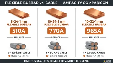
Ampacity consolidation is the key space-saving benefit:
- A single 10 × 24 × 1 mm flexible busbar rated for 770A at 50°C temperature rise replaces two 400 kcmil cables or three 3/0 conductors
- A 10 × 32 × 1 mm configuration rated 965A substitutes for two 600 kcmil or three 300 kcmil cables
- A 5 × 24 × 1 mm busbar rated 510A replaces one 600 kcmil cable or two 3/0 conductors
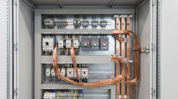
This consolidation means fewer cable glands, less bundling, and simpler routing in tight enclosures. The PVC jacket allows routing in areas where rigid busbar fabrication would be impractical—around obstructions, through offset planes, or between stacked components—eliminating the engineering and fabrication time associated with custom-bent rigid bus.
Time and Cost Advantages
Each connection point costs less and installs faster with flexible busbars: the exposed laminate ends are drilled or punched and bolted directly to rigid bus or equipment terminals, eliminating ring terminals and crimped lugs entirely. For panel shops building multiple identical units, this advantage compounds with every termination.
Replacing a rigid busbar design with flexible busbar removes the time spent measuring, cutting, forming, and fitting rigid bus segments. Manufacturers report that flexible busbar systems install up to 50% faster than busduct or cable tray with multiple cables and lugs, with total installed cost reductions of 20% minimum. Siemens documented 40% assembly time savings when adopting laminated busbars in industrial drive systems.
Performance and Operating Advantages
Flexible busbars present greater contact surface area at connection points due to the flat laminate stack. Larger contact area directly reduces connection resistance—and therefore heat—compared to round cable lugs of equivalent ampacity. As contact area increases, joint resistance drops, lowering operating temperatures and improving long-term reliability.
Beyond thermal performance, the laminated structure provides inherent vibration resistance. Solid rigid bus can crack under cyclic stress; cable lugs can loosen. The flexible laminate construction absorbs vibration without degrading electrical performance—making it well-suited for panels mounted near rotating machinery, pumps, or drives in manufacturing, oil and gas, and municipal water treatment environments.
Key Applications for Flexible Copper Busbars in Industrial Power Distribution Panels
Flexible copper busbars are deployed wherever routing flexibility, space savings, or installation speed matter. Primary panel types include:
- Motor Control Centers (MCCs): Routing between vertical sections and branch connections
- Variable Frequency Drive (VFD) Systems: DC bus connections, filter chokes, and input/output terminations
- Switchboards: Main bus to branch bus transitions, especially in retrofit upgrades
- Transformer Connections Within Panels: Secondary distribution where space is constrained
- UPS Systems: Battery-to-inverter and inverter-to-distribution connections
- Panelboards: Feeder taps and sub-feed distributions in large enclosures
Each of these panel types involves at least one routing challenge that flexible busbar addresses directly: tight bends, offset planes, vibration exposure, or the need to avoid custom fabrication.
Industrial Sectors
Three sectors account for a large share of flexible busbar demand in industrial settings:
- Manufacturing facilities: Machine tool panels, process control enclosures, and conveyor drive systems
- Municipal water treatment plants: Pump control panels where high humidity and vibration are constant factors
- Oil and gas operations: Hazardous-location enclosures requiring compact, reliable power distribution in harsh environments
Demand is also growing in newer application areas. Renewable energy inverter panels and data center power distribution units (PDUs) present the same space and installation constraints where flexible busbars deliver measurable results as system densities rise. A documented solar energy case study achieved a 40% footprint reduction using flexible laminated bus in AC combiners and recombiners.
How to Size Flexible Copper Busbars for Power Distribution Panels
Determining Required Ampacity
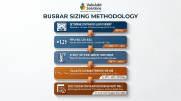
Start with the continuous load current the busbar must carry. NEC 210.19(A)(1) requires that conductors for continuous loads (operating for 3 hours or more) be sized for 125% of the continuous load current. For a 400A continuous load, the conductor must be rated for at least 500A.
Flexible busbars are rated at multiple temperature rise levels — typically 30°C, 50°C, and 70°C above ambient. Selecting a lower rise gives a more conservative design with less heat at terminations. Because the PVC jacket is rated to 105°C and UL 508A sets a typical industrial panel ambient of 40°C, your selected temperature rise plus the enclosure ambient cannot exceed 105°C.
Practical Sizing Example:
- Load: 400A continuous
- Apply NEC Rule: 400A × 1.25 = 500A required conductor rating
- Enclosure Ambient: Assume 50°C (elevated due to other heat-generating equipment)
- Allowable Rise: 105°C (jacket limit) - 50°C (ambient) = 55°C maximum
- Select Configuration: Using a 50°C temperature rise table, choose a busbar rated ≥ 500A. A 5 × 24 × 1 mm configuration provides 510A at 50°C rise
Two levers control current-carrying capacity in the configuration notation:
- Laminates (N): Doubling from 5 to 10 roughly doubles ampacity
- Cross-section (W × T): Increasing width or thickness raises capacity proportionally
Substituting Cable with Flexible Busbar
The sizing example above works well for new installs. When retrofitting or upgrading existing panels, a cable substitution reference table lets you match your current cable arrangement directly to an equivalent busbar configuration.
| Flexible Busbar (N × W × T) | Ampacity @ 50°C Rise | Cable Equivalent |
|---|---|---|
| 6 × 9 × 0.8 mm | 250A | 1 × 3/0 or 2 × #3 AWG |
| 6 × 15.5 × 0.8 mm | 350A | 1 × 350 kcmil or 2 × 1/0 |
| 5 × 20 × 1 mm | 435A | 1 × 400 kcmil or 2 × 2/0 |
| 5 × 24 × 1 mm | 510A | 1 × 600 kcmil or 2 × 3/0 |
| 10 × 24 × 1 mm | 770A | 1 × 2000 kcmil or 2 × 400 kcmil |
| 10 × 32 × 1 mm | 965A | 2 × 600 or 3 × 300 kcmil |
ValuAdd's UL Listed Isoflexx® and Ultraflexx® flexible copper busbars come with published ampacity data and configuration specifications that speed up configuration selection. ValuAdd's technical support team can assist system integrators and panel builders in matching the correct configuration to specific load and enclosure requirements.
Installation and Connection Best Practices for Panel Builders
Fabrication: Bending, Twisting, and Cutting
Minimum bend radius rule: The bend radius must be ≥ 1/2 inch, or 1/8 inch multiplied by the number of laminates, whichever is greater. Violating the bend radius risks delamination and increased resistance at the bend, which leads to localized heating and eventual failure.
Recommended forming procedure:
- Strip the PVC jacket on one end to expose the laminates
- Clamp the laminates firmly (they must not shift)
- Drill bolt holes in the exposed end
- Insert a temporary holding bolt
- Form the busbar into the desired shape
- Cut and strip the second end
- Clamp, drill, and bolt the second termination
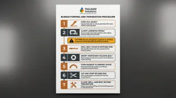
Why clamp during drilling? Without clamping, the laminates ride up the drill bit, creating uneven holes and poor contact surface when bolted.
Twist limitation: Flexible busbars should not be twisted more than 90 degrees along their length. A 90-degree twist requires a minimum length of at least three times the total busbar width (including the jacket) to avoid mechanical stress. Excessive twist distorts the laminate stack and creates uneven current distribution.
Making the Electrical Connection
Surface preparation is critical. The mating surface must be flat (not polished), clean, and free of oxide and grease before bolting. Copper oxide layers increase contact resistance and operating temperature. Research confirms that progressive oxide buildup creates a "vicious circle" where increased resistance generates heat, which accelerates further oxidation, ultimately causing joint failure from overheating.
Overlap requirements: The recommended overlap is at least 5 times the total laminate stack thickness. Below that threshold, the streamline effect (current crowding at the joint edge) concentrates stress on a small contact area; at 5× overlap, that crowding disperses rapidly and contact resistance drops to acceptable levels.
Bolt size and torque values:
| Bolt Size | Recommended Torque |
|---|---|
| 1/4-20 | 9 lb-ft |
| 5/16-18 | 18 lb-ft |
| 7/16-14 | 50 lb-ft |
| 1/2-13 | 75 lb-ft |
| 9/16-12 | 110 lb-ft |
| 5/8-11 | 150 lb-ft |
Use SAE Grade 5 bolts with flat and contact washers on both sides of the connection. Under-torquing leads to high contact resistance; over-torquing can crush the laminates or crack the insulation. Confirm final torque values against your specific hardware grade and the busbar manufacturer's documentation before signing off on the connection.
Frequently Asked Questions
What is the difference between flexible busbar and cable?
Flexible busbars use stacked flat copper laminates rather than stranded round conductors, allowing direct bolted termination without lugs, a tighter bend radius, and greater contact surface area at connections. A single busbar can replace multiple cable runs at equivalent ampacity, saving space and installation time.
How to calculate busbar size for panel?
Start with the continuous load current multiplied by 1.25 per NEC requirements, then select a flexible busbar configuration whose rated ampacity at the appropriate temperature rise exceeds that value. Factor in panel ambient temperature as well — the sum of ambient plus temperature rise must not exceed the insulation's 105°C rating.
What are flexible copper busbars used for?
Common applications include:
- Motor control centers and VFD enclosures
- Switchboards and panelboards
- Transformer connections and UPS systems
- Tight enclosures and high-vibration environments
Anywhere routing flexibility, space savings, or reduced installation time is a priority, flexible copper busbars are a practical choice.
What are the different types of copper busbars?
The four main types are:
- Rigid copper busbar — fixed shape, machined for permanent installations
- Flexible laminated copper busbar — stacked foil in a PVC jacket for tight routing
- Tinned copper busbar — corrosion-resistant surface treatment
- Braided copper busbar — woven strands for maximum flexibility and vibration absorption
What is a busbar on a panel?
A busbar in a power distribution panel is the main conductor bar that receives incoming power and distributes it to branch circuits or connected equipment. It serves as the electrical backbone of the panel and is typically made from copper or aluminum, available in rigid or flexible configurations.