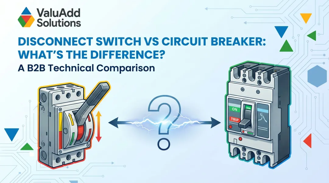
Introduction
In industrial facilities—from manufacturing plants to water treatment operations—two types of switching devices often sit side-by-side in distribution panels: load break switches and disconnect switches. They may look similar from the outside, but confusing the two or misapplying one in place of the other can trigger arc flash incidents, destroy equipment contacts, or force costly unplanned downtime when a circuit fails during switching.
For engineers and system integrators designing medium voltage switchgear or motor control panels, choosing the right device has direct consequences across three areas:
- Operational continuity — can you isolate sections without shutting down the entire facility?
- Personnel safety — will the device safely interrupt the arc during switching?
- Code compliance — does it meet IEC 60947-3, NEC Article 430, and OSHA lockout/tagout requirements?
This article breaks down what each device does, where the functional differences matter in real applications, and how to choose between them.
Key Takeaways
- Load break switches safely interrupt live circuits under load; disconnect switches only isolate circuits that have already been de-energized
- Arc interruption capability is the core divide—load break switches include quenching mechanisms; disconnects do not
- Using a disconnect switch on a live circuit risks arc flash, contact welding, and injury
- Application split: Load break switches for operational switching; disconnect switches for maintenance isolation and lockout/tagout
- Switch selection turns on circuit state, voltage level, switching frequency, and standards compliance (IEC 60947-3, NEC, OSHA)
Load Break Switch vs. Disconnect Switch: Quick Comparison
The table below breaks down the core differences across five key attributes to help you select the right switch for your application.
| Attribute | Load Break Switch | Disconnect Switch |
|---|---|---|
| Breaking Capability | Rated breaking capacity; interrupts load current safely | No breaking capacity; must only operate on de-energized circuits |
| Arc Management | Incorporates arc extinguishing (air, SF6, or vacuum) | No arc quenching — designed so no arc is generated |
| Construction | Double-break contacts, arc chambers, complex mechanism | Simple design with visible open gap as primary safety feature |
| Primary Application | Operational switching in energized systems | Safety isolation during maintenance or inspection |
| Safety Rule | Can be operated under load | Must only be operated on a confirmed de-energized circuit — operating under load risks arc flash and device failure |
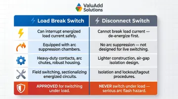
The critical takeaway: these switches are not interchangeable. Using a disconnect switch to interrupt a live circuit is a serious safety violation that can cause arc flash injuries and equipment damage.
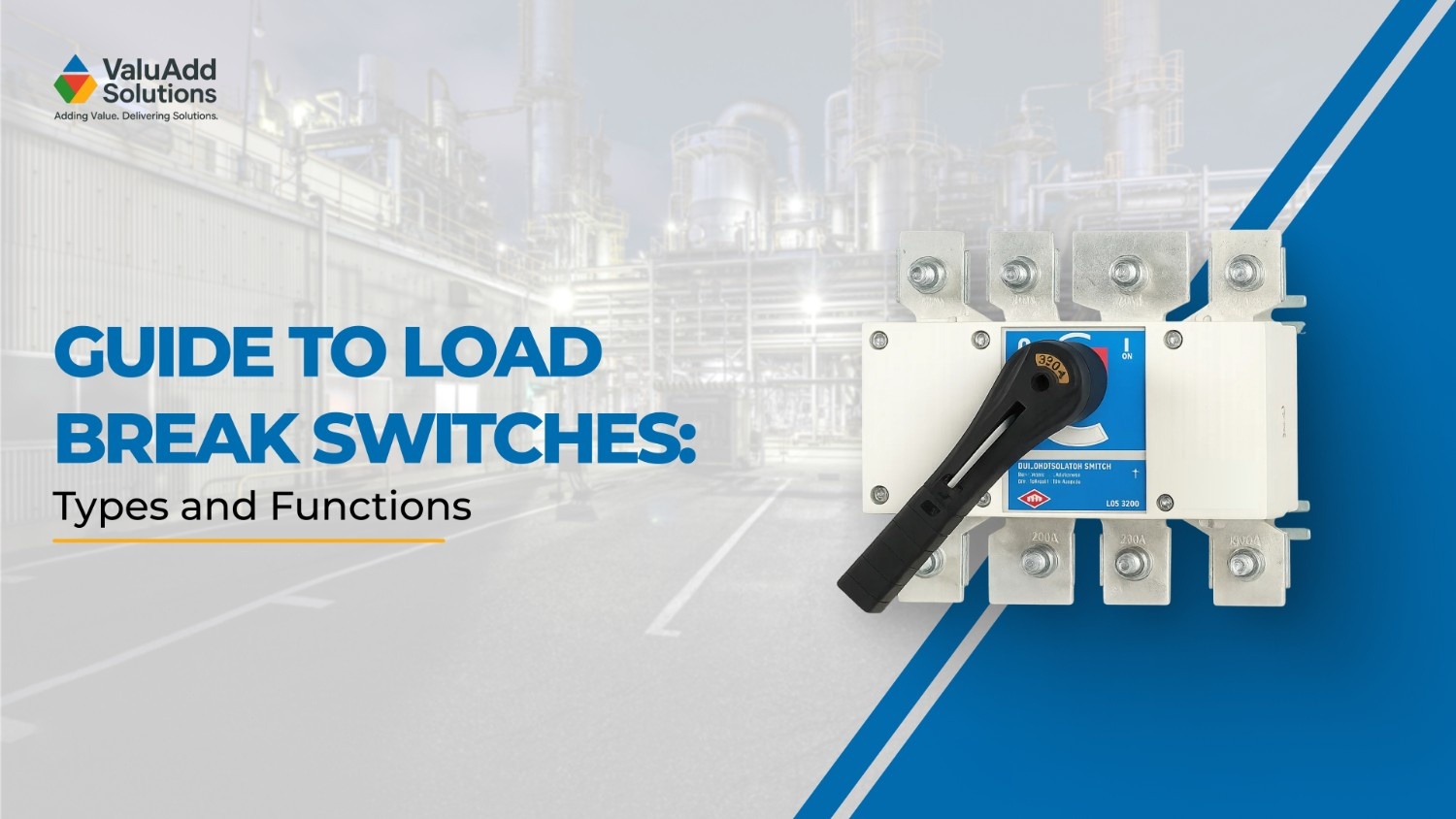
What is a Load Break Switch?
A load break switch is a mechanical switching device designed to make, carry, and break electrical circuits under normal energized and loaded conditions. Governed by IEC 60947-3, it is rated by utilization categories—AC-21, AC-22, and AC-23—that define its suitability for resistive, mixed, and motor/inductive loads respectively.
How Arc Extinguishing Works
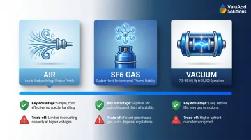
When the contacts of a load break switch separate under load, current is transferred to sacrificial arcing contacts while the main contacts are protected. The arc is then extinguished using one of three media—air blast, SF6 gas, or vacuum—depending on the voltage level and design. This enables circuits to be switched without de-energizing adjacent systems, giving operators section-by-section control over the facility.
Arc interruption media by application:
- Air — Common in low-to-medium voltage panels; uses a puffer and nozzle system (ABB VersaRupter)
- SF6 — Sealed units for harsh outdoor environments; strong thermal stability but carries high global warming potential
- Vacuum — Medium voltage (7.2 kV to 38 kV); preferred for frequent switching, rated up to 30,000 cycles
IEC 60947-3 Utilization Categories
| Category | Application | Making Current | Breaking Current | Power Factor |
|---|---|---|---|---|
| AC-21A/B | Resistive loads | 1.5 × Ie | 1.5 × Ie | 0.95 |
| AC-22A/B | Mixed resistive/inductive | 3 × Ie | 3 × Ie | 0.65 |
| AC-23A/B | Motor/inductive loads | 10 × Ie | 8 × Ie | 0.45 (≤100A), 0.35 (>100A) |
Of these, the Class E2 rating represents the highest endurance classification—confirming a switch can handle frequent switching cycles without degraded performance. ValuAdd's CFMVRMX Series Medium Voltage Soft Starters carry Class E2 certification and include integrated bypass and isolation contactors that maintain load break capability while protecting connected motors during start/stop sequences.
Operational Benefits
Load break switches allow maintenance and reconfiguration on specific circuit segments without de-energizing the entire system. According to Siemens' True Cost of Downtime 2024 report, unplanned downtime costs the world's 500 largest companies 11% of their yearly revenues—totaling $1.4 trillion annually. The cost of a lost hour averages $260,000 across all manufacturing sectors. Load break switches reduce this risk by enabling partial system isolation.
Use Cases of a Load Break Switch
Where load break switches fit in industrial operations:
- Medium voltage distribution switchgear for sectionalizing power networks
- Motor feeder circuits requiring frequent start/stop control
- Automated production line control panels with continuous operation requirements
- Distribution networks in manufacturing facilities and water treatment plants
Industries that rely on load break switches:
- Oil and gas facilities switch between circuits during live operations without triggering a full shutdown
- Industrial manufacturing plants isolate production line sections individually to maintain uptime elsewhere
- Utility distribution operators manage load transfers without causing widespread outages
- Water treatment facilities control pump and blower motors through normal operational switching cycles
For these applications, ValuAdd carries load break switches certified to UL 98B and IEC 60947-3 standards — including the SIRCO UL 98 C (rated up to 800V AC, 400–1000A) and the INOSYS LBS UL 98B (750 VDC breaking capacity per pole for DC, PV, and ESS applications).
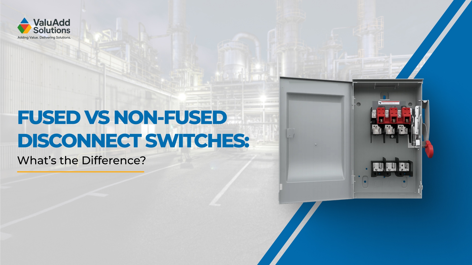
What is a Disconnect Switch?
A disconnect switch (also called an isolator or disconnector) is a mechanical device designed to provide a visible, physical break in the circuit for isolation purposes, confirming that a section of the electrical system is completely de-energized before personnel perform inspection, maintenance, or repair. Under IEC 60947-3, it corresponds to utilization category AC-20A/B and carries no rated breaking capacity.
Key Design Features
- Visible open gap: Provides confirmation of isolation, critical for lockout/tagout compliance
- No arc extinguishing chamber: Not designed to break current
- Lockout provisions: Includes provisions for padlocking in the OFF position
Two US standards directly govern how disconnect switches are applied in practice. OSHA 29 CFR 1910.147 defines an "energy isolating device" as a mechanical device that physically prevents energy transmission and must be capable of being locked out. Separately, NFPA 70E Article 120.6 requires workers to "visually verify that all blades of the disconnecting devices are fully open" when establishing an electrically safe work condition — which is precisely why the visible open gap matters.
Critical Safety Rule
Because a disconnect switch has no arc quenching capability, it must never be operated under load. Operating under load causes uncontrolled arcing because there is no arc quenching capability. This can damage contacts, trigger arc flash, or injure personnel. NFPA estimates 5 to 10 arc flash explosions occur daily in the US. IEC 60947-3 requires devices in utilization categories AC-20A/AC-20B to be marked "Do not operate under load" unless interlocked to prevent such operation.
Use Cases of a Disconnect Switch
Disconnect switches are the right tool when current has already been interrupted and the priority is safe, visible isolation:
- Upstream isolation points ahead of maintenance zones in switchboards and control cabinets
- Main disconnects on machinery where the system is powered down before switching
- Visible isolation confirmations in lockout/tagout safety programs
- Service entrance disconnects where an upstream breaker has already interrupted current
NEC and OSHA lockout/tagout requirements make visible isolation a compliance requirement in many industrial settings. Disconnect switches provide the lockable open-circuit gap needed to meet these standards.
Key Differences That Matter for Industrial Applications
Breaking Capacity and Arc Management
Breaking capacity is what separates these two devices at the design level. Load break switches carry a rated breaking capacity—the current they can safely interrupt—and are built with arc quenching systems. IEC 60947-3 mandates that AC-23A load break switches must make 10× rated operational current and break 8× rated current. Disconnect switches carry no breaking capacity rating because they are not intended to interrupt current—they simply provide a mechanical open-circuit gap.
For system integrators specifying switchgear, this distinction directly affects protection coordination design. The load break switch handles operational switching; the disconnect switch provides the visible isolation point downstream.
Operating Conditions
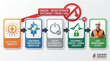
Load break switches: Can be actuated while the circuit is live and carrying rated current.
Disconnect switches: Must only be actuated after the circuit has been confirmed de-energized by an upstream switching device.
Practical implication: In a facility where partial system isolation is needed without full shutdown, only a load break switch is appropriate for the switching action. The disconnect switch comes after, providing the lockable isolation point for maintenance access.
Construction and Lifespan
The two devices are rated differently because their operational roles differ:
- Load break switches: Rated for electrical lifespan in thousands of operations per utilization category (per IEC standards), built for repeated energized switching
- Disconnect switches: Carry a mechanical lifespan rating only — no electrical lifespan, because current interruption is outside their intended function
- Key risk: Energized switching on a disconnect switch degrades contacts rapidly and puts the installation out of safety compliance
Protection and Integration
Load break switches can be integrated with fuses or other protective elements to provide load switching plus overcurrent protection in a single device (fused load break switch). ValuAdd's RMS Modular Fuse Holders support high breaking capacity fuses up to 100 kA rms, combining switching and overcurrent protection in a compact form. Disconnect switches, by contrast, provide no protective function. They are isolation-only devices.
Standards and US Compliance
Both device types fall under IEC 60947-3 internationally, but US industrial environments often reference:
- NEC Article 430: Motor disconnecting means requirements—must have an ampere rating of at least 115% of full-load current and be located in sight from the motor controller
- NEMA enclosure ratings: NEMA Type 4X, Type 12, IP66, IP68 for environmental protection
- OSHA 29 CFR 1910.147: Lockout/tagout requirements dictating when visible isolation is required
UL 98 covers enclosed switches used as branch, feeder, service, and motor circuit disconnecting means. UL 508 covers industrial control equipment and is restricted to use as manual motor disconnects when marked as such.
Which Switch Should You Choose?
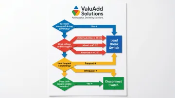
The right choice depends on four factors engineers should evaluate before specifying either device:
- Is the circuit energized during switching? If yes, only a load break switch is safe to operate.
- What is the voltage level and load type? Motor loads, resistive, or mixed? This maps directly to IEC utilization categories.
- How frequently will switching occur? Frequent cycling favors a load break switch; infrequent isolation-only events suit a disconnect switch.
- Does code require visible isolation? OSHA LOTO or NEC requirements may mandate a disconnect switch downstream.
Clear Situational Recommendations
Choose a load break switch when:
- Switching under load is required
- Medium/high voltage distribution applications
- Motor circuit control with operational switching
- Circuit must remain partially live during switching
- Frequent switching operations are expected
Choose a disconnect switch when:
- Sole purpose is confirmed isolation for maintenance access
- An upstream device has already de-energized the circuit
- Visible, lockable open gap is required by code
- Infrequent operation (maintenance cycles only)
For ValuAdd's industrial customers in manufacturing facilities, water treatment plants, and oil and gas operations, load break switches rated to Class E2 endurance standards (such as the CFMVRMX Series) are the appropriate choice for operational switching points. Disconnect switches serve the isolation function downstream, providing the visible, lockable gap required for OSHA compliance.
Real-World Scenario
A 2020 incident documented by OSHA Inspection 125860.015 illustrates what's at stake. Two electrical contractors replacing wiring at a commercial building came into contact with 480 volts in an electrical disconnect panel, causing an arc flash. Both were hospitalized with severe burns. Disconnect switches must never be operated under load, and visible isolation must be confirmed before work begins.
That risk is not ambiguous. Schneider Electric explicitly warns that a disconnector is "not designed to make or to break current" and is "essentially a dead system switching device to be operated with no voltage on either side of it." Operating one under load can result in a "bad arc" that damages equipment and endangers personnel.
Frequently Asked Questions
What is a load break disconnect switch?
A load break disconnect switch (also called a switch disconnector) is a combined device that handles both functions: it can switch under load and provide isolation with a visible open gap, making it a single-unit solution for applications requiring both operational switching and code-compliant isolation.
What is the purpose of a load break switch?
Its primary purpose is to safely make and break electrical circuits while they are energized and carrying current. It uses arc extinguishing mechanisms (air, SF6, or vacuum) to protect the circuit, equipment, and operator during switching—so operations can continue without a full system shutdown.
What is the difference between a breaker and a load break switch?
A circuit breaker provides automatic fault protection (thermal and magnetic trip for overloads and short circuits), while a load break switch only provides manual switching under load with no automatic protection. Breakers are for fault interruption; load break switches are for controlled operational switching.
Is an isolator a disconnect?
Yes. An isolator and a disconnect switch (disconnector) refer to the same device: a mechanical isolation device that provides a visible, safe open-circuit gap on a de-energized circuit for maintenance, with no load-breaking capability. The terms are interchangeable.
What is the difference between a disconnect switch and an air break switch?
An air break switch is a type of load break switch that uses air as the arc-interrupting medium when breaking a live circuit. A disconnect switch does not interrupt live circuits at all. The two terms are not interchangeable: one is a load-interrupting device, the other is an isolation-only device.