Introduction
When a utility interruption strikes an industrial facility, the consequences escalate rapidly. Manufacturing lines halt mid-cycle, water treatment pumps lose pressure, and critical process equipment begins an uncontrolled shutdown. The financial impact compounds by the minute.
The greater danger, though, lies in how power is restored. An uncontrolled source changeover creates serious safety risks: backfeed into the utility grid can electrocute line workers, out-of-phase reconnection damages motors and drives, and simultaneous connection of two sources can trigger catastrophic equipment failure.
According to IEEE 399 (Brown Book), industrial motor loads introduce inrush currents up to 6 times full-load amps during restart, making controlled power transfer essential. A manual transfer switch (MTS) provides the deliberate, operator-controlled mechanism to redirect electrical load between utility power and backup generators — or between dual utility feeds — while physically preventing dangerous parallel source connections.
Selecting the right MTS for an industrial environment requires far more than matching amp ratings. Voltage class, load type, environmental protection, and code compliance all determine whether your switching equipment protects your facility or introduces new failure points.
Key Takeaways
- Manual transfer switches physically isolate one power source before connecting another, preventing dangerous backfeed into utility grids
- NEC Article 702 permits MTS for optional standby systems; life-safety loads require automatic transfer switches instead
- UL 1008 listing is mandatory for industrial MTS units; Withstand and Closing Ratings (WCR) must match upstream overcurrent protection
- Size switches and generators for motor inrush — typically 6x the running current at startup
- NEMA 4X enclosures provide washdown and corrosion protection for harsh environments
What Is a Manual Transfer Switch and How Does Source Changeover Work?
A manual transfer switch is a mechanical switching device that isolates an electrical load from one power source and connects it to a second source through deliberate operator action. In industrial settings, "source changeover" typically means switching between utility power and an on-site backup generator, between dual utility feeds from separate substations, or between utility and UPS systems during planned maintenance or unplanned outages.
The critical safety feature of an MTS is its break-before-make configuration: the switch physically opens the circuit connection to the primary source before establishing connection to the secondary source. This open-transition design prevents dangerous backfeed into the utility grid, which could electrocute utility workers performing restoration, and protects downstream equipment from fault currents that result from paralleling unsynchronized sources.
ValuAdd's SIRCOVER UL manual transfer switches use a double-breaking-per-pole design with sliding bar contact mechanisms, providing enhanced safety and durability during load switching operations.
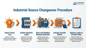
Typical Industrial Changeover Sequence:
- Detect power loss — Operator confirms utility interruption through panel indicators or SCADA monitoring
- Isolate sensitive loads — Critical motor loads are shut down in controlled sequence to prevent inrush overload on backup source
- Start and stabilize backup source — Generator reaches rated voltage and frequency (typically 10-30 seconds)
- Actuate transfer switch — Operator manually moves switch handle from "Line" to "Generator" position
- Restore loads in priority order — Equipment is energized sequentially, managing motor starting inrush within generator capacity
The open-transition operation creates a brief dead-bus period (typically 5-30 seconds depending on operator response and generator start time). For most industrial applications, this interruption is acceptable. However, certain load types are highly sensitive to this gap:
- Variable Frequency Drives (VFDs) can experience damaging inrush if reconnected before residual voltage decays
- Process control systems may require ride-through UPS for continuity
- Synchronized motors need time to coast down before safe reconnection
Closed-transition switching, which momentarily parallels sources for seamless transfer, is reserved for microprocessor-controlled automatic transfer switches and is not applicable to standard manual switches.
Understanding these load sensitivities helps clarify why the physical construction of an MTS matters — each component plays a direct role in safe, reliable switching.
Key Components of a Manual Transfer Switch Assembly
Industrial MTS assemblies rated for three-phase 480V/600V service incorporate several essential components:
- Switching mechanism: Rotary cam-operated or molded-case toggle design. Rotary mechanisms offer rugged quick-make/quick-break action for frequent portable generator connections; molded-case designs provide integral overcurrent protection and higher Withstand and Closing Ratings for permanent installations.
- Enclosure: NEMA-rated protective housing — Type 1 for clean indoor electrical rooms, Type 12 for dust and dripping water on manufacturing floors, Type 4X for corrosive or washdown environments like water treatment facilities.
- Busbars and lug connections: Heavy-duty copper or aluminum conductors sized for full continuous current rating, with mechanical lug terminals accommodating appropriate wire sizes.
- Position indicators: Clear visual confirmation of switch position (Line/Off/Generator); advanced models include mechanical interlocks that prevent handle movement while under load without deliberate override.
- Metering and monitoring (optional): Voltage/current indicators, hour meters, or communication interfaces for remote monitoring.
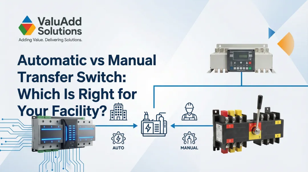
Manual Transfer Switch vs. Automatic Transfer Switch: Which Is Right for Your Application?
The fundamental operational difference comes down to initiation. An MTS requires a human operator to physically actuate the switch. An ATS uses a microprocessor controller to sense power loss and transfer automatically — within milliseconds to seconds. Neither is universally superior; the correct choice depends on application criticality, staffing model, and regulatory requirements.
Industrial Scenarios Where MTS Is the Better Choice:
- Staffed manufacturing facilities with 24/7 operator presence where SOPs require human oversight of each transfer
- Non-critical auxiliary loads — HVAC, lighting, or office circuits where brief interruptions are tolerable
- Cost-sensitive projects where MTS units offer lower initial purchase price and minimal ongoing maintenance
- Planned maintenance windows requiring deliberate switching between utility and generator for load bank testing or commissioning
- Load sequencing applications where operators must control the order and timing of load restoration to protect generator capacity
When ATS is required, the distinction is usually regulatory — NEC article classification removes the choice entirely.
Scenarios Where ATS Is Required:
- NEC Article 700 Emergency Systems mandate automatic transfer equipment for life-safety loads like egress lighting and fire pumps
- Article 701 Legally Required Standby systems supporting emergency responders must transfer automatically — no manual option is permitted
- Unmanned remote facilities such as pump stations, pipeline compressors, or substations where no on-site personnel are available
- Critical continuous processes — hospital HVAC, data centers, or pharmaceutical manufacturing — where interruptions exceeding seconds create unacceptable operational or safety risk
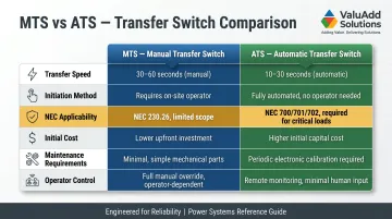
Technology Comparison:
| Feature | Manual Transfer Switch | Automatic Transfer Switch |
|---|---|---|
| Transfer Speed | Operator-dependent (10–60 seconds typical) | Fast (under 10 seconds typical) |
| Initiation | Human operator | Microprocessor controller |
| NEC Applicability | Article 702 (Optional Standby) only | Articles 700, 701, 702 |
| Initial Cost | Lowest | Moderate to high |
| Maintenance | Minimal (mechanical inspection only) | Moderate (controller testing required) |
| Operator Control | Complete manual oversight | Limited to emergency override |
Key Industrial Applications for Manual Transfer Switches
Manufacturing Facilities
Manufacturing plants use MTS units to protect production equipment during planned utility maintenance or unplanned grid interruptions. The key advantage is controlled restart sequencing: operators can energize motor control circuits, conveyor systems, and process equipment in the correct order, preventing simultaneous motor starting that would overload the backup generator. ValuAdd's SIRCOVER UL switches, rated up to 1200A at 600V in 3-pole and 4-pole configurations, handle the high-current demands these environments place on switching equipment.
Municipal Water and Wastewater Treatment
Water treatment and pumping stations represent a critical MTS application where operator oversight ensures safe motor load sequencing. When grid power fails, pump motor feeds must be transferred to backup generators without creating dangerous inrush overload conditions. A single large pump can draw 6× its full-load current for several seconds during startup — attempting to start multiple pumps simultaneously on generator power causes voltage collapse and contactor dropout. MTS units allow operators to restore pumps sequentially, managing generator transient capacity within safe limits.
Oil and Gas Facilities
Wellhead control panels, pipeline compression stations, and process skids often require MTS units as deliberate operator intervention points — keeping personnel in the loop before any source transfer occurs. These environments also introduce stricter specification requirements beyond standard industrial switches:
- NEMA 4X enclosures for corrosion resistance in coastal or H2S-rich atmospheres
- Hazardous location certifications for classified zones per NEC Article 500/505 and API RP 500
ValuAdd's portfolio addresses these requirements with NEMA Type 4X compliant enclosures and UL-listed switching mechanisms rated for the electrical loads common across upstream and midstream oil and gas operations.
System Integrator Custom Control Panels
Electrical system integrators frequently specify MTS units as components within larger custom-engineered control panels. The compact design and simple wiring connections of modern industrial switches make them ideal for integration into process skids, mobile equipment, or packaged power distribution systems. For integrators, ValuAdd provides comprehensive technical documentation, CAD files, and pre-sales engineering support — reducing the selection and configuration work before a panel ever reaches the shop floor.
How to Size and Select a Manual Transfer Switch for Industrial Use
Amperage Sizing
The MTS continuous current rating must equal or exceed the total simultaneous load. Calculate total load current by summing the full-load amperage from equipment nameplates for all devices that will operate concurrently on the alternate source. NEC Article 702.4 explicitly requires transfer equipment to have adequate capacity for all equipment intended to operate simultaneously.
Critical sizing principle: Do not confuse continuous rating with Withstand and Closing Rating (WCR). UL 1008 requires transfer switches to survive specific fault current levels tied to the clearing time of upstream overcurrent protection devices. A 400A continuous-rated switch, for example, may carry a WCR of 65,000A at 0.050 seconds — but only when coordinated with the correct upstream breaker. Verify that coordination before specifying the switch.
Voltage Rating Requirements
Confirm the system voltage class before specifying equipment:
- Single-phase 120/240V — Residential and light commercial only; not suitable for industrial motor loads
- Three-phase 208V — Small commercial applications
- Three-phase 480V — Standard industrial distribution voltage in North America
- Three-phase 600V — Heavy industrial and some utility applications
ValuAdd's SIRCOVER UL manual transfer switches support voltages up to 600 VAC in 3-pole and 4-pole configurations, appropriate for the vast majority of industrial installations. Specifying below system voltage is a safety violation; specifying well above it adds unnecessary cost without engineering benefit.
Motor Load Considerations
Industrial motors draw approximately 6 times full-load amps during starting (NEMA Code G locked-rotor current). This inrush affects MTS sizing in two distinct ways:
- Switch closing capability — The MTS must close into motor starting inrush without contact welding or mechanical damage. UL 1008 Withstand and Closing Rating tests verify this capability.
- Generator sizing coordination — Backup generators typically produce twice their continuous kVA rating at 0.4 power factor to handle motor starting. If voltage dip during start exceeds 20–30%, magnetic contactors will drop out and the motor will fail to accelerate.
Treat the MTS, generator, and motor as a coordinated system — size them together, not independently.

Circuit Configuration
Match switch poles to load requirements:
- 2-pole — Single-phase 240V loads
- 3-pole — Three-phase delta systems or three-phase loads with separate neutral
- 4-pole — Three-phase wye systems requiring switched neutral for ground fault protection
Industrial Certifications and Standards to Look For
UL 1008 Listing
UL 1008, "Transfer Switch Equipment," is the definitive safety standard for transfer switches up to 1000V. It covers both automatic and manual (non-automatic) transfer switches, requiring rigorous testing: temperature rise, dielectric voltage-withstand, overload endurance, and short-circuit withstand/closing capability.
Verify the listing specifically references UL 1008 — not just "UL Listed." Generic claims often reference UL 98 (enclosed switches), which does not address transfer-specific hazards like backfeed prevention and source coordination. ValuAdd's manual transfer switch products carry UL 1008 listing (UL Guide WPYV File E317092).
NEMA Enclosure Ratings
Match enclosure type to installation environment:
| NEMA Type | Protection Level | Industrial Application |
|---|---|---|
| Type 1 | Indoor, basic protection against falling dirt | Clean electrical rooms |
| Type 12 | Indoor, dust, lint, fibers, dripping water | Manufacturing floors, machining areas |
| Type 3R | Outdoor, rain, sleet, ice | Standard outdoor installations |
| Type 4X | Indoor/outdoor, hose-directed water, corrosion-resistant | Water treatment, coastal facilities, chemical plants |
ValuAdd's SIRCOVER manual transfer switches are available with NEMA Type 4X and Type 12 compliant enclosures, providing appropriate protection for demanding indoor and outdoor industrial environments.
NEC Article Compliance
The National Electrical Code establishes strict boundaries on where manual transfer equipment is permitted:
- Article 700 (Emergency Systems) — Automatic transfer mandatory; MTS prohibited
- Article 701 (Legally Required Standby) — Automatic transfer mandatory; MTS prohibited
- Article 702 (Optional Standby Systems) — MTS permitted for property protection and process continuity where life safety is not dependent on performance
Ensure your application falls under Article 702 before specifying manual transfer equipment. Life-safety systems require automatic transfer switches regardless of staffing or operational preference.
Hazardous Location Requirements
Oil and gas facilities, chemical plants, and environments with flammable gases or combustible dusts require equipment certified for hazardous locations per NEC Articles 500/505 and API RP 500/505. Two classification systems apply:
- NEC 500 (Class/Division) — classifies areas by material type and likelihood of hazardous atmosphere presence
- NEC 505 (Zone) — uses Zone-based classification aligned with IEC international standards
MTS units installed in classified areas must either carry a UL/CSA hazardous location listing for the specific classification, or be housed in NFPA 496 purged and pressurized enclosures that maintain positive pressure to prevent hazardous gas ingress.
Installation and Safety Best Practices
Industrial MTS installation must be performed by a licensed electrician or qualified electrical engineer in accordance with the NEC, local electrical codes, and manufacturer instructions. Most US jurisdictions require permits and inspections — verify requirements with your local Authority Having Jurisdiction (AHJ) before beginning work.
Critical Safety Rules:
Lockout/Tagout (LOTO) compliance — OSHA 1910.147 requires de-energizing and locking out all upstream sources before making connections. Isolate and tag both utility and generator sources.
Verify source stability — Confirm the backup generator has reached rated voltage and frequency before completing transfer. An unstable source at switchover risks equipment damage.
Never parallel sources on open-transition MTS — MTS units are break-before-make devices only. Closing both sources simultaneously creates catastrophic fault current and severe injury risk.
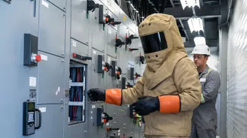
Arc flash hazard — NFPA 70E requires arc flash risk assessment and rated PPE before operating energized equipment. MTS switching under load is a live arc flash hazard — PPE is non-negotiable.
Load sequencing documentation — Document SOPs covering load shutdown sequence, generator startup verification, transfer execution, and load restoration priority before the first live transfer.
Frequently Asked Questions
What is a manual transfer switch?
A manual transfer switch is a mechanical switching device that allows an operator to manually redirect electrical load from a primary power source to a backup or alternate source through deliberate handle actuation. The switch uses break-before-make operation to physically isolate sources, preventing dangerous backfeed into utility grids.
What's the difference between ATS and STS?
An ATS (Automatic Transfer Switch) uses electromechanical contactors and microprocessor control to transfer power automatically, typically within 10 seconds. An STS (Static Transfer Switch) uses solid-state electronics (SCRs/thyristors) for near-instantaneous switching under 4 milliseconds — no moving parts, primarily for UPS and mission-critical loads. Both differ from an MTS, which requires deliberate operator action to initiate the transfer.
Do I need a permit to install a manual transfer switch?
In most US jurisdictions, installing a transfer switch requires an electrical permit and inspection by the Authority Having Jurisdiction (AHJ). Many jurisdictions also require the work to be performed by a licensed electrician. Contact your local building department to verify specific permit requirements before beginning installation.
What is the correct amperage rating for a manual transfer switch?
The MTS amperage rating must equal or exceed maximum continuous load current — calculated by summing full-load amps from all equipment nameplates running simultaneously. Motor loads also require inrush consideration (typically 6x rated current) when sizing the MTS alongside the generator and upstream protection.
Can a manual transfer switch prevent backfeed into the utility grid?
Yes. An MTS using break-before-make switching physically isolates the load from the utility before connecting the backup source, creating a brief dead-bus period that prevents backfeed — protecting utility workers during grid restoration and eliminating the risk of paralleling unsynchronized sources.