Introduction
For industrial facilities—manufacturing plants, water treatment operations, and processing facilities—an unplanned power transition can mean lost production, damaged equipment, or compromised safety systems. The U.S. industrial sector bears 26% of an estimated $80 billion annual national outage cost, which makes reliable backup power a financial and operational necessity.
Selecting the wrong ATS size ranks among the most consequential electrical decisions a facility manager will make. ATS sizing involves utility service ratings, load classification, NEC compliance, and industrial-specific demands like motor inrush current — not simply matching amps to a generator. Undersized or mismatched switches create code violations and reliability failures precisely when backup power is needed most.
This guide walks through how to calculate facility load, understand NEC load priority classifications, and evaluate the key specification factors that determine the right ATS for your application.
What is an Automatic Transfer Switch (ATS)?
An Automatic Transfer Switch (ATS) is a self-acting device that monitors the primary (utility) power source and automatically transfers connected loads to a backup source—typically a generator—within seconds of detecting a loss of utility power. Once utility power is restored and stable, the ATS returns those loads to the primary source without manual intervention.
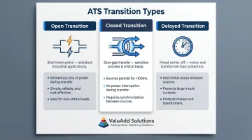
Three Main ATS Transition Types:
| Transfer Type | Operation | Industrial Application |
|---------------|-----------|------------------------|
| Open Transition | Break-before-make with brief interruption during transfer | Standard for most industrial applications where momentary power interruption is acceptable |
| Closed Transition | Make-before-break with momentary paralleling of sources (less than 100 milliseconds) | Preferred for sensitive process loads requiring seamless transfer; requires synchronized sources |
| Delayed Transition | Break-before-make with timed center-off position | Motor loads and transformers; allows residual voltages to dissipate and motors to wind down |
Core Functions of an ATS in an Industrial Setting
An industrial ATS performs continuous voltage monitoring on both utility and backup sources, detecting undervoltage, phase loss, phase reversal, and phase imbalance. The switch coordinates with the generator's control system to verify stable output before completing a transfer, protecting sensitive industrial equipment from being transferred onto an unstable source.
Key operational benefits for industrial facilities:
- Eliminates manual intervention during outages
- Protects loads from voltage irregularities
- Enables selective coordination capability for multi-priority load systems
- Ensures regulatory compliance for life safety and critical operations circuits
For facilities requiring high fault-current ratings and remote monitoring, ValuAdd carries the ATyS FT by Socomec — a fully automatic open transition transfer switch rated up to 100 kA short-circuit withstand, with RS485 Modbus communication for direct connection to SCADA and building management systems.
How to Calculate the Right ATS Size for Your Facility
The Foundational Rule: Size to Utility Service, Not Generator Output
Critical requirement: An ATS must be sized to the utility service entrance rating (the main breaker amperage)—not the generator's output rating. Sizing to the generator instead creates a dangerous mismatch where the ATS may be undersized for the actual service current, resulting in code violations, overheating, and potential failure under full utility load.
A documented industry case study highlights an installation where an ATS with a 50 kA withstand and closing rating (WCR) was rejected by an inspector because the "as installed" available fault current was calculated at 52 kA, resulting in severe change order costs and project delays.
Three-Phase Industrial Load Calculation
For three-phase systems (the most common utilization voltage in U.S. industrial facilities is 480V), use this formula:
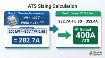
Amps = kW × 1,000 ÷ (Volts × √3 × Power Factor)
Worked Example:
- Load: 200 kW
- Voltage: 480V three-phase
- Power Factor: 0.85
Calculation: 200 × 1,000 ÷ (480 × 1.732 × 0.85) = 200,000 ÷ 707.472 = 282.7 Amps
The NEC 80% Continuous Load Rule
NEC Sections 210.19(A)(1) and 240.20(A) mandate that equipment handling continuous loads (operating 3 hours or more) must be rated so the actual load does not exceed 80% of the rated capacity. This is a code requirement, not a design preference.
Practical application: A facility with a calculated continuous load of 160A requires a 200A-rated ATS, not a 160A unit.
In our 282.7A example above, applying the 80% rule: 282.7 ÷ 0.80 = 353.4A minimum ATS rating. Select the next standard rating: 400A ATS.
Demand Factor and Diversity Factor
Not all equipment runs simultaneously in industrial facilities with many motors and machines. IEEE 141 defines:
- Demand Factor: Ratio of maximum coincident demand to total connected load (typically 0.6–0.85 depending on facility type)
- Diversity Factor: Ratio of sum of individual non-coincident maximum demands to maximum demand of the complete system
Applying demand factors prevents over-specification while ensuring the switch handles realistic peak loads. Always consult a licensed electrical engineer to determine the appropriate demand factor for your specific facility type and load profile.
Motor Inrush Current Considerations
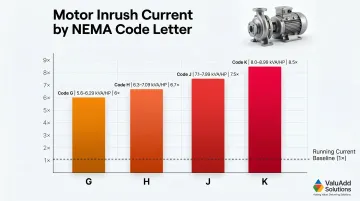
Once demand factors are established, motor inrush becomes the next critical variable. Motors draw far more current during startup than during normal operation— NEMA MG 1 establishes Code Letters to classify motors by the ratio of locked-rotor kVA per horsepower:
| NEMA Code Letter | kVA/HP with Locked Rotor | Approximate Multiple |
|---|---|---|
| G | 5.6 - 6.29 | ~6× running current |
| H | 6.3 - 7.09 | ~6.7× running current |
| J | 7.1 - 7.99 | ~7.5× running current |
| K | 8.0 - 8.99 | ~8.5× running current |
For facilities with large motors (pumps, compressors, HVAC), this surge must be factored into transfer switch sizing. The ATS must be rated to withstand this inrush without nuisance tripping or contact damage.
Key Factors to Consider When Selecting an Industrial ATS
The calculated amperage is the starting point, but the final ATS selection for an industrial or commercial facility must account for multiple operational, regulatory, and environmental factors that vary significantly between applications.
Amperage Rating and Service Entrance Configuration
Matching the ATS to the utility service entrance rating is non-negotiable. If the facility has a 400A main breaker, the ATS must be rated for 400A.
Critical distinction:
- Service entrance-rated ATS: Includes its own main disconnect and must be marked "Suitable for Use as Service Equipment" (SUSE); suitable for connecting directly to the utility feed
- Non-service entrance-rated ATS: Requires a separate main disconnect upstream; used for sub-panels or partial-facility backup
Facilities with multiple electrical panels may require multiple ATS units: one per panel, or a single higher-rated ATS upstream. This decision impacts cost, maintenance burden, and code compliance.
Load Type: Resistive vs. Inductive Loads
Resistive loads (lighting, heating, most electronics) draw consistent current and are straightforward to size. Inductive loads (motors, pumps, compressors, VFD-driven equipment) create starting current surges and power factor challenges.
For manufacturing and processing facilities where motors dominate the load profile, the ATS must be rated for the inductive duty cycle and verified to handle motor starting load without dropout.
VFD Considerations: Facilities using variable frequency drives introduce harmonic distortion into the power system. Standard six-pulse VFDs generate harmonic distortion, requiring ATS selection that confirms compatibility with the harmonic profile and IEEE 519 compliance requirements. For facilities that need to meet those thresholds, 18-pulse drive designs—such as the Benshaw H2 519/519P Series available through ValuAdd—achieve less than 8% THDv and 5% TDDi out of the box.
Voltage Configuration and Phase Requirements
Most U.S. industrial facilities operate on 480V three-phase service, while commercial facilities commonly use 208V or 240V single-phase or three-phase. The ATS must be specified for the correct voltage and phase configuration; mismatching can result in equipment damage or system failure.
Three-phase ATS units are available in configurations compatible with both wye and delta systems. The facility's existing service configuration determines which is required.
Load Priority Classification and NEC Code Compliance
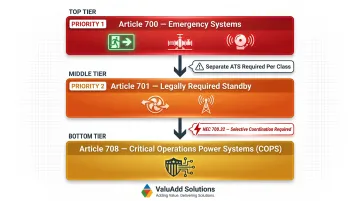
NFPA 70 (NEC) defines three classes of generator-backed loads:
| NEC Article | Load Class | Examples |
|---|---|---|
| Article 700 | Emergency Systems | Life safety loads: egress lighting, fire pumps, fire alarms |
| Article 701 | Legally Required Standby | Smoke control, public safety systems, emergency responders |
| Article 708 | Critical Operations Power Systems | National security or critical process continuity |
Facilities with multiple load classes are typically required to install separate ATS units per class to ensure fault isolation and load prioritization. NEC 700.32 requires emergency system overcurrent protective devices be selectively coordinated. In practice, this means a fault on a lower-priority circuit must clear without tripping protection on emergency or legally required standby branches.
Separate ATS units per load class inherently achieve this isolation. Failing to segregate loads by class can result in code violations and jeopardize life safety system reliability during an outage.
Enclosure Rating and Environmental Suitability
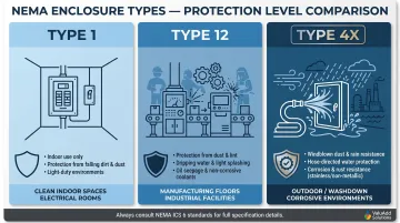
The installation environment determines the required NEMA enclosure rating:
| NEMA Type | Protection Level | Industrial Application |
|---|---|---|
| Type 1 | Indoor use; protects against falling dirt | Clean, climate-controlled electrical rooms |
| Type 12 | Indoor use; protects against circulating dust, lint, dripping water, seepage of oil/non-corrosive coolants | Manufacturing floors, machining areas |
| Type 4X | Indoor/outdoor use; protects against windblown dust, hose-directed water, provides increased corrosion protection | Water treatment, chemical processing, washdown areas, outdoor installations |
Selecting an ATS with an inadequate enclosure rating for the actual operating environment accelerates component degradation and creates reliability and safety risks.
For ATS-adjacent components in these environments, ValuAdd carries NEMA Type 4X and Type 12 rated products—including the SW Series Washdown Drives with UL Type 4X (IP66) polycarbonate enclosures—designed specifically for washdown and corrosive exposure conditions.
Future Load Growth and Scalability
Facilities planning equipment additions, production line expansions, or EV charging infrastructure should size the ATS with a growth buffer—typically specifying the next standard amperage rating above the current calculated load.
Example: A facility currently at 320A calculated load should consider a 400A ATS rather than a 350A unit. The cost difference is marginal compared to the expense of replacing the ATS when loads increase.
Scalability also applies to the number of ATS units. A facility that initially backs up only critical loads may later need to add backup for additional load groups. Planning conduit pathways, panel space, and generator capacity in advance of the second ATS reduces future installation costs considerably.
How ValuAdd Can Help
ValuAdd supplies industrial control, automation, and electrical components for demanding industrial environments—including ATS-compatible electrical solutions. The engineering team, with backgrounds in plant engineering and system integration, helps facilities match components to their specific load profiles, voltage configurations, and compliance requirements.
Relevant Credentials and Capabilities:
- UL Listed products meeting national safety standards
- NEMA Type 4X and Type 12 enclosures rated for harsh industrial environments
- Class E2 load break rating for reliable disconnect operation
- IEEE 519 compliant components for harmonic-sensitive environments with VFD loads
- CE/FCC certified for internationally compliant installations
These certifications are directly relevant to industrial ATS selection—particularly for manufacturing, water treatment, and oil and gas applications where equipment reliability and environmental protection are critical.
Competitive Advantages:
- Provides territory-based technical sales support and hands-on component selection assistance
- Covers industrial control, power distribution, and monitoring needs within a single portfolio
- Ships quickly for urgent installations or replacement scenarios
- Delivers load profile-specific recommendations tailored to your facility's compliance requirements
Contact ValuAdd's engineering team for application-specific sizing guidance and technical consultation.
Conclusion
Selecting the right ATS for an industrial facility is a multi-variable decision. Accurate load calculation and utility service matching are the starting point, but the final specification also depends on:
- Load type (resistive vs. inductive vs. harmonic-generating)
- Voltage configuration and available fault current
- NEC code classification (optional, legally required, or critical)
- Environmental conditions (NEMA enclosure rating, temperature range)
- Future growth plans and load expansion
Facilities that treat ATS sizing as a simple amperage lookup risk code violations, equipment failure, and loss of backup power at exactly the wrong moment.
ATS selection doesn't end at installation. As facilities expand, load profiles shift, and equipment upgrades introduce new inductive loads or harmonic sources. Periodic review of the ATS specification against actual facility conditions keeps the backup power system reliable and NEC-compliant. When reassessing your system, work with a qualified electrical engineer and a component supplier who can match switching capacity, transfer time, and enclosure ratings to your specific facility requirements.
Frequently Asked Questions
How do I know what size transfer switch I need?
Size the ATS to match the utility service entrance rating (main breaker amperage), not the generator. For three-phase systems: Amps = kW × 1,000 ÷ (Volts × √3 × Power Factor). Then apply the NEC 80% continuous load rule — a 400A service requires a 400A-rated ATS.
How many amps do I need for a transfer switch?
The required amp rating equals the utility service size. For example, a 200A service requires a 200A ATS. For continuous loads (operating 3+ hours), size up per the 80% NEC rule, meaning a 160A continuous load requires a 200A-rated ATS to remain code-compliant.
Can I use a transfer switch with a different amp rating than my service?
The ATS must be rated at or above the service entrance ampacity. Using an undersized ATS is a code violation and a fire hazard. A higher-rated ATS is permissible but adds cost without operational benefit.
What size transfer switch do I need for a 10,000-watt generator?
For a single-phase 240V system, 10,000W ÷ 240V = approximately 42A. With the 80% rule applied, a 50A-rated transfer switch is the appropriate minimum size for this generator output.
What size generator do I need for a 30-amp transfer switch?
A 30A transfer switch at 240V supports up to approximately 7,200 running watts (30A × 240V). The generator should be rated at 7,200W or less to match this switch capacity, with motor surge/starting watts accounted for.
What is the 80% rule for generators?
The NEC requires that continuous loads (running 3+ hours) not exceed 80% of rated equipment capacity. For ATS sizing, your connected load must stay at or below 80% of the switch's amperage rating to remain code-compliant and prevent overheating.