Introduction
When a poorly insulated busbar arcs inside an industrial control panel, the consequences escalate fast: fault current spreads across adjacent conductors, circuit breakers trip, production lines halt, and maintenance crews face hours of downtime diagnosis. A minor oversight in standoff insulator selection can cost thousands in lost production and emergency repairs.
Standoff insulators serve a dual engineering function: they physically separate live busbars from grounded enclosure structures while bearing substantial mechanical loads, including static conductor weight and the electromagnetic forces generated during short-circuit events. These components must maintain precise electrical clearance distances and creepage paths for the system voltage, per IEC 60664-1.
This guide covers standoff insulator materials, types, and the selection criteria engineers need for industrial panel builds in water treatment, oil and gas, and manufacturing environments.
TLDR:
- Standoff insulators prevent electrical flashover while withstanding short-circuit forces often exceeding 20 kN
- Material choice matters: cycloaliphatic epoxy suits harsh outdoor use; DMC/BMC works for indoor panels
- Size by matching clearance/creepage to voltage class (IEC 60664-1) and mechanical loads (IEC 60865-1)
- Support spacing must account for fault current levels; high-fault systems (65 kA) need closer standoff intervals
- UL 508A compliance is mandatory for U.S. industrial control panels — material ratings must align
What Are Stand-Off Insulators and How Do They Work?
A busbar standoff insulator is a rigid, non-conductive component that physically separates a live busbar from grounded enclosure structures. It maintains two critical dimensions: creepage distance (the shortest path along the insulator surface) and clearance (the shortest distance through air). Both must meet or exceed minimum values dictated by the system voltage.
Electrical Isolation Mechanism
The insulator body creates a a high-resistance path (measured in teraohms) that prevents leakage current from reaching ground. Creepage distance matters because surface contamination (dust, moisture, conductive residue) can form a leakage path over time. Clearance through air provides immediate dielectric strength against voltage surges.
IEC 60664-1 Edition 3.0 (2020) governs insulation coordination for equipment up to 1,000 V AC or 1,500 V DC. The standard specifies minimum clearance based on rated impulse withstand voltage (Uimp) and altitude. For example, a 480 V industrial motor circuit (Overvoltage Category III) requires a Uimp of 4,000 V, translating to a minimum clearance that increases at elevations above 2,000 meters.
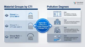
Creepage distance is determined by the material's Comparative Tracking Index (CTI) and the environment's Pollution Degree. Key relationships:
- CTI ≥ 600 V (Material Group I): Shortest permitted creepage distances; suited for clean indoor environments
- Pollution Degree 1–2: Clean or slightly contaminated indoor spaces; allows reduced creepage margins
- Pollution Degree 3–4: Industrial or outdoor sites with conductive contamination; requires longer creepage paths
- Lower CTI materials: Demand proportionally longer surface paths to achieve equivalent tracking resistance
Electrical isolation addresses only one half of the design equation. The other is structural — standoff insulators must also withstand the physical forces generated during fault events.
Mechanical Support Under Short-Circuit Stress
Standoff insulators bear static busbar weight plus intense dynamic forces. During a three-phase short circuit, adjacent busbars carrying fault current experience electromagnetic repulsion. The peak force ($F_m$) scales with the square of the peak short-circuit current ($i_p^2$) and inversely with phase spacing ($a$).
For a typical 65 kA short-circuit current in a low-voltage switchgear with 100 mm phase spacing and 500 mm span length, the electromagnetic force can exceed 20 kN (4,500 lbf) per support. This cantilever load can crack improperly rated insulators or shift busbar alignment, creating new fault paths.
Post Geometry and Ribbed Profiles
Cylindrical or post designs distribute compressive stress evenly across the mounting base. Ribbed or disk-type profiles extend the surface creepage distance without increasing overall height—allowing compact panel designs while maintaining electrical safety. However, IEC rules specify that grooves narrower than 1 mm are ignored in creepage calculations, as the electrical path effectively "bridges" them.
Profile geometry determines how much height and surface area a standoff occupies in a panel — which directly influences how components are selected and combined.
Standoff Insulators vs. Busbar Support Clamps
A standoff insulator rigidly mounts the busbar to a back panel or mounting rail at a fixed height, providing electrical isolation. A busbar support clamp grips and holds the conductor itself, often incorporating mechanical tension or clamping force. Most industrial panel designs use both: standoffs for voltage isolation and clamps for mechanical retention along long busbar runs.
Materials Used in Stand-Off Insulators
Material selection drives insulator performance in specific environments. Each material offers distinct trade-offs between dielectric strength, mechanical rigidity, thermal stability, cost, and environmental resistance.
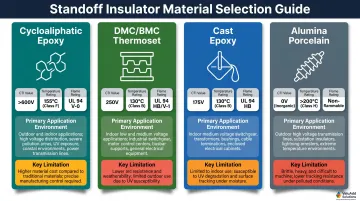
Epoxy Resin (Cast Epoxy)
Cast epoxy resin dominates indoor low- and medium-voltage panels due to its high dielectric strength (>580 V/mil), excellent mechanical rigidity (flexural strength 17,400–21,700 psi), and resistance to common industrial chemicals. Halogen-free epoxy formulations meet fire-safety requirements for enclosed panel environments, emitting minimal toxic smoke during fire events. Thermal Class F ratings allow continuous operation at elevated temperatures typical of switchgear applications.
DMC/BMC (Dough/Bulk Molding Compound)
These glass fiber-reinforced thermoset plastics combine high compressive strength (up to 20,000 lbf) with dimensional stability at significantly lower cost than cast epoxy. UL 94 V-0 flame ratings ensure the material self-extinguishes quickly, making DMC/BMC a practical fit for high-volume low-voltage distribution panels. Operating temperatures typically range from 120 °C to 130 °C.
Porcelain/Ceramic
Porcelain insulators withstand extreme continuous temperatures, offer superior surface hardness, and resist UV degradation and weathering indefinitely. Compressive strength exceeds 590 MPa, and the material is non-combustible. Despite being heavier and more brittle than polymer alternatives, porcelain remains the preferred choice for outdoor switchgear, substations, and high-voltage applications where long-term outdoor exposure is a given.
Cycloaliphatic Epoxy (HCEP)
Cycloaliphatic epoxy offers exceptional tracking and erosion resistance in humid or contaminated environments. CTI values exceed 600 V, and the material passes IEC 60587 Class 1A tests—the most demanding standard for surface discharge resistance. That makes it the preferred specification for coastal installations, water treatment plants, chemical processing facilities, and oil and gas operations. In these environments, moisture, salt fog, or chemical vapors accelerate degradation of standard epoxy.
Material Comparison Summary
| Material | Key Strength | Typical Application | Limitation |
|---|---|---|---|
| Cycloaliphatic Epoxy (HCEP) | CTI > 600 V; exceptional tracking resistance; IEC 60587 Class 1A | Outdoor, high humidity, severe pollution (coastal, water treatment, chemical plants) | Higher cost; UL 94 V-1 (not V-0) |
| DMC/BMC Thermoset | High compressive strength (20,000 lbf); UL 94 V-0; cost-effective | Indoor low/medium-voltage panels, standard busbar supports | Lower temperature limit (120-130 °C) |
| Cast Epoxy (Bisphenol-A) | High dielectric strength (>580 V/mil); Thermal Class F | Indoor MV switchgear bushings, post supports | Less tracking-resistant than cycloaliphatic |
| Alumina Porcelain (C120/C130) | Non-combustible; extreme UV/weather resistance; 590 MPa compressive | Outdoor substations, corrosive environments, extreme temperatures | Heavy; brittle; higher installation labor cost |
Types of Stand-Off Insulators for Busbar Panel Applications
Industrial panel insulators are categorized by mounting function and geometry, not generic insulator families. Understanding the functional types helps match components to specific panel layout requirements.
Cylindrical Post / Standoff Insulators
These single-post insulators feature threaded inserts on both ends for direct busbar-to-back-panel mounting. They serve as the workhorse component for single-phase or multi-phase busbar systems where each conductor requires independent isolation. ValuAdd's Male-Female Hexagonal Insulators, for example, support voltage ranges from 500 VAC/DC to 2,400 VAC/VDC with M8 screw connections and UL 94 V0-rated materials.
Busbar Clamp / Support Insulators
Multi-phase frame-style supports hold multiple busbars at defined phase-to-phase spacing intervals. These components ensure consistent electrical clearance across long runs while simplifying installation. ValuAdd's SB P 30 Busbar Support provides 185 mm phase spacing for 3-pole configurations and 123 mm for 4-pole systems, optimized for space-constrained switchboard applications.
Feed-Through / Wall Bushings
When power must pass between compartments or through grounded panel barriers, feed-through bushings provide a rated insulation path. These specialized insulators accommodate conductors penetrating metal enclosure walls while maintaining voltage isolation and preventing arcing at the penetration point.
Spool / Shackle Insulators
Used primarily in lower-voltage service entry or overhead conductor applications, spool insulators support conductors under tension. While less common in modern enclosed panel designs, they remain relevant for open-air busbar runs in industrial facilities.
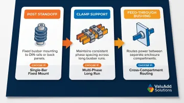
Selection Driver: Match the insulator type to the specific mounting task:
- Post standoffs — fixed busbar mounting to DIN rails or back panels
- Clamp supports — maintaining consistent phase spacing across long busbar runs
- Feed-throughs — routing power between separate enclosure compartments
ValuAdd's standoff insulator portfolio carries UL Listed, CE-certified, and Halogen Free ratings — so system integrators can confirm compliance at the component level before the panel ships.
Busbar Mounting and Panel Design: Key Considerations
Proper standoff selection and placement requires balancing electrical safety standards, mechanical fault loads, thermal expansion, and environmental enclosure ratings.
Phase Spacing and Creepage/Clearance Requirements
Standoff height must achieve the minimum clearance and creepage distances required by system voltage and applicable standards. For U.S. industrial panels, UL 508A and IEC 60664-1 provide the framework. Under-sized standoffs are a primary cause of in-service flashover.
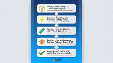
Process:
- Identify the system voltage and Overvoltage Category (typically Category III for fixed industrial equipment)
- Determine the rated impulse withstand voltage (Uimp) from IEC 60664-1 Table F.1
- Calculate minimum clearance from Table F.2 or F.8, applying altitude correction factors if needed
- Calculate minimum creepage from Table F.5 based on working voltage, Pollution Degree, and material CTI
- Select a standoff height that provides both required dimensions with margin for mechanical tolerance
Mounting Orientation: Vertical vs. Horizontal Busbars
Standoff insulators behave differently under gravity and fault loads depending on busbar orientation. Vertical busbar runs transfer fault forces axially into the mounting surface as compressive loads—the strongest load direction for most insulator geometries. Horizontal runs create cantilever bending moments at the standoff base, requiring higher bending load ratings.
Selection Impact: Verify that the insulator's published compressive load rating (for vertical) or cantilever/bending load rating (for horizontal) exceeds calculated static and dynamic loads with an appropriate safety factor (typically 2:1 minimum).
Thermal Expansion Management
Copper expands approximately 17 µm per meter per °C; aluminum expands roughly 23 µm per meter per °C. Over a 3-meter busbar run with a 50 °C temperature rise, that translates to 2.5 mm of expansion for copper and 3.5 mm for aluminum.
Rigidly clamping both ends transfers cumulative stress into standoff insulators, risking fracture over repeated thermal cycles.
Design Practice: Designate one end or the center of a long busbar run as a fixed anchor point with rigid standoffs. Use sliding or spring-loaded supports at the opposite end to allow longitudinal expansion. Major switchgear manufacturers like Siemens (SIVACON 8PS) and Schneider Electric (Canalis KR) mandate this approach in their installation guides.
Short-Circuit Bracing Intervals
Support spacing along a busbar run must be calculated based on rated short-circuit current. Closer spacing reduces the unsupported span and the bending moment under fault forces, preventing permanent busbar deformation or insulator failure.
IEC 60865-1 provides the calculation methodology: electromagnetic force between parallel busbars is proportional to the square of the peak fault current and span length, and inversely proportional to phase spacing.
For a 65 kA system, support spacing must be tighter than for a 40 kA system to keep mechanical stress within acceptable limits. Two verification paths apply under IEC 61439-1 Annex P:
- Full short-circuit test: Required for new designs without precedent
- Comparison to reference design: Assemblies can skip full testing when busbar supports match the type, shape, material, and spacing of a previously tested design
Environmental and Enclosure Ratings
Beyond mechanical and electrical requirements, the panel environment determines both the enclosure rating and which standoff materials hold up long-term:
- NEMA Type 12: Indoor use; protects against circulating dust, falling dirt, and dripping non-corrosive liquids. Standard DMC/BMC thermosets or cast epoxies are sufficient.
- NEMA Type 4X: Indoor/outdoor use; watertight, dust-tight, and corrosion-resistant. Requires UV-stable, tracking-resistant materials like cycloaliphatic epoxy or porcelain, plus stainless steel or heavily plated metal inserts.
How to Select the Right Stand-Off Insulator for Your Application
Follow this structured approach to match insulator specifications to system requirements.
Step 1: Confirm Voltage Class
Verify the insulator's rated voltage and impulse withstand voltage (BIL) meet or exceed the system's maximum voltage including transients. Distinguish between continuous voltage rating (steady-state operation) and short-duration withstand rating (surge or fault conditions).
For low-voltage systems (<1,000 V AC), reference IEC 60664-1. For medium-voltage systems (>1 kV), use IEEE C62.82.2 to select the appropriate Basic Lightning Impulse Insulation Level (BIL) and Basic Switching Impulse Insulation Level (BSL).
Step 2: Match Material to Environment and Compliance
Use the material comparison table to drive selection based on these three factors:
- Select by temperature: DMC/BMC handles up to 120–130 °C; porcelain suits extreme-temperature environments
- Match to exposure: cast epoxy for indoor clean installations; cycloaliphatic epoxy or porcelain for outdoor, humid, or UV-exposed locations
- Confirm certifications: UL listing for U.S. industrial panels (UL 508A and NEC Article 409), CE marking for EU Low Voltage Directive compliance, halogen-free per IEC 61249-2-21 for fire-safe applications
For U.S. industrial panel builders, UL listing is a procurement and inspection requirement. Supplement SA 3.3 to UL 508A explicitly requires polymeric mechanical parts supporting live parts to comply with Section 13 (Insulating Materials).
Step 3: Verify Mechanical Ratings Against Calculated Loads
Calculate static busbar weight plus dynamic fault-force loads using IEC 60865-1 methodology, then confirm the insulator's published ratings exceed those values with an appropriate safety factor. Three ratings require verification:
- Compressive load — weight-bearing capacity under static busbar loads
- Cantilever (bending) load — resistance to lateral fault forces along the busbar
- Tensile load — pull-out strength at mounting points
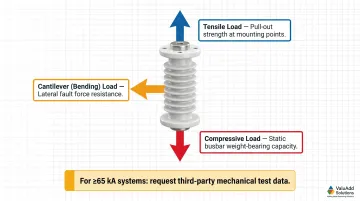
For high fault-current systems (≥65 kA), request load test data or third-party mechanical test reports from suppliers. Generic kN/m rule-of-thumb values are insufficient for proper verification under IEC 61439-1 Annex P.
Frequently Asked Questions
What is a standoff insulator?
A standoff insulator is a rigid, non-conductive component that physically separates a live conductor (such as a busbar) from a grounded surface. It provides both electrical isolation and mechanical support, maintaining the clearance and creepage distances required for your system voltage.
What are the 4 types of insulators?
By function, the four broad categories are pin, suspension, strain, and post/standoff. By material, common types include ceramic/porcelain, epoxy, polymer/composite, and glass. For busbar and industrial panel work, post/standoff insulators and busbar support-clamp types are most relevant.
How do I size a standoff insulator for my busbar system?
Sizing involves two steps:
- Match the insulator's voltage rating and height to required creepage/clearance distances per IEC 60664-1 or UL 508A.
- Verify that its compressive, bending, and tensile load ratings exceed the busbar weight plus calculated short-circuit forces.
What is the difference between a standoff insulator and a busbar support clamp?
A standoff insulator is a single rigid post that elevates and electrically isolates the busbar from the mounting surface at a defined height. A busbar support clamp grips and mechanically holds the conductor itself. Many panel designs use both components together for complete support.
Can standoff insulators be used in outdoor or harsh industrial environments?
Yes. Porcelain and cycloaliphatic epoxy (a high-performance resin) standoffs are rated for outdoor or contaminated environments due to their superior UV resistance, moisture tolerance, and tracking resistance per IEC 60587. Indoor epoxy and DMC/BMC types are better suited for protected enclosures with controlled environmental conditions.
What certifications should I look for when specifying standoff insulators for industrial panels?
UL listing is typically required for U.S. industrial control panels per NEC Article 409 and UL 508A. CE marking is mandatory for European compliance under the Low Voltage Directive 2014/35/EU. Halogen-free certification (IEC 61249-2-21) matters for fire-safe or enclosed environments where low smoke and toxicity are critical.