
Introduction
When an electrical engineer opens a switchgear panel in an industrial facility, the first thing they notice are thick metallic bars connecting the incoming power supply to rows of circuit breakers—those bars are busbars. Despite being one of the most fundamental components in power distribution, busbars work without fanfare, carrying thousands of amperes through substations, motor control centers, and industrial machinery.
For anyone specifying electrical infrastructure, understanding busbars is essential. In high-current applications above 1,000 A, engineers face a direct choice: run unwieldy parallel cable bundles that complicate maintenance and fault location, or deploy rigid busbar systems that deliver superior current capacity, heat dissipation, and installation simplicity.
The case for busbars is well-documented. Cable-based designs can cost nearly 60% more in capital expenditures compared to busway systems, while requiring approximately 32% more copper for equivalent ampacity.
This guide walks through what busbars are, how they work, the key material and configuration choices, and when they outperform cable in industrial applications.
Key Takeaways
- A busbar is a rigid metallic conductor—typically copper or aluminum—that distributes electrical power from a single source to multiple circuits within switchgear, panels, and industrial equipment
- Copper offers higher conductivity; aluminum is lighter and lower cost—both are commonly plated to resist oxidation and reduce contact resistance
- Common configurations include single, double, and ring busbar systems
- Physical forms range from flat rigid bars and tubular designs to laminated flexible busbars
- Busbars are specified over cables when high current capacity (≥1,000 A), space efficiency, and heat dissipation are the priority
What Is a Busbar and How Does It Work?
Defining the Busbar
A busbar is a flat, rigid metallic strip or bar housed inside switchgear enclosures, panelboards, or bus duct assemblies. Cross-sectional dimensions vary widely—from compact bars a few millimeters thick in control panels to massive tubular conductors spanning outdoor substation structures.
The busbar's primary function is to act as an electrical junction point. It collects incoming current from a power source (transformer, generator, or utility service) and distributes it to multiple outgoing circuits or loads through taps, bolted connections, or clamps. Rather than requiring individual point-to-point wiring for each circuit, the busbar serves as a shared, low-resistance conductor backbone.
The Operating Principle
Current flows through the busbar along the path of least resistance. The busbar's large cross-sectional area keeps both resistance and heat generation low compared to equivalently rated cables — an advantage that compounds as current demands increase into the hundreds or thousands of amperes.
Skin effect considerations: At AC utility frequencies (50–60 Hz), current concentrates near the conductor's outer surface rather than distributing uniformly. This skin effect means that solid bars thicker than about 8 mm become less efficient, as the interior material contributes little to conduction while adding weight and cost. Engineers address this by specifying flat, hollow, or laminated profiles that maximize surface area relative to total volume.
The AC-to-DC resistance ratio ($R_{ac}/R_{dc}$) serves as a critical design parameter, helping engineers optimize conductor geometry to minimize resistive losses and heat generation under alternating current.
Mounting and cooling: Most busbars are uninsulated metal, mounted on insulated standoffs or pillars inside a grounded enclosure. This arrangement allows convective air cooling across the entire surface, improving heat dissipation compared to bundled cables.
The open design also simplifies circuit expansion. Maintenance teams can bolt a new tap directly to the bar's surface without splicing or pulling additional conductors.
Types of Busbars Explained
By System Configuration
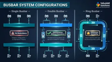
Single busbar system: All sources and loads connect to one common bar — the simplest and most economical configuration. It offers no redundancy, so a fault or scheduled maintenance shuts down the entire system. Suitable only for non-critical applications or where backup power isn't required.
Double busbar system: Two parallel busbars allow any source or load to be switched between bars via isolators or circuit breakers. Maintenance teams can work on one bus while the other stays energized, eliminating downtime. Standard in substations and industrial facilities where continuous uptime justifies the added complexity.
Ring busbar (ring main) system: Busbars form a closed loop, so power reaches any point from two directions. If one section faults or needs isolation, supply continues from the opposite direction — a topology that measurably improves reliability. Widely deployed in utility distribution networks and large industrial complexes where redundancy is mandatory.
By Shape and Construction
| Construction Type | Key Advantage | Typical Application |
|---|---|---|
| Rigid flat bar | Best balance of conductivity, cost, and ease of installation | Switchgear, panelboards, fixed indoor installations |
| Laminated/flexible busbar | Bends around obstacles; absorbs vibration and thermal cycling | Motor drives, generators, high-vibration environments |
| Round and tubular busbar | High stiffness-to-weight ratio; better current distribution under skin effect | High-voltage substations, outdoor switchyards, transmission |
| Single-phase busbar | Simple design; one live conductor plus neutral | Light commercial, non-industrial distribution |
| Three-phase busbar | Handles industrial load distribution across three phase conductors | Industrial facilities, processing plants, substations |
A few construction details worth knowing:
- Rigid flat bars can be bent, drilled, and punched during fabrication, making them adaptable without specialized tooling.
- Laminated busbars bond multiple thin strips with insulating layers, increasing surface area for heat dissipation while preventing mechanical fatigue where rigid bars would crack.
- Tubular busbars improve current distribution under skin effect conditions — an important consideration at higher voltages where current migrates to the conductor's outer surface.
- Three-phase systems require proper phase spacing and support insulation to prevent short circuits and maintain balanced load distribution across all three bars.
Busbar Materials: Copper, Aluminum, and Protective Coatings
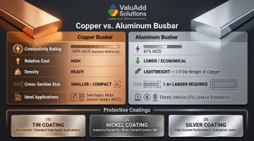
Copper: Copper has the second-highest electrical conductivity of all metals (after silver), making it the default choice for high-current industrial busbars where minimizing resistance and heat generation is the priority. It delivers superior performance per unit cross-section but is denser and more expensive than aluminum. For critical switchgear and motor control centers where space is constrained and reliability is non-negotiable, copper remains the preferred material.
Aluminum: Aluminum is the fourth-most conductive metal and roughly one-third the weight of copper. This makes it attractive where weight reduction matters: EV battery packs, large outdoor substation busbars, and overhead bus ducts. To match the current capacity of a copper bar, an aluminum busbar requires a larger cross-section — typically 1.6 times the area.
Aluminum also forms a thin oxide layer on exposed surfaces, which can increase contact resistance at bolted joints. Engineers address this with special joint preparation, contact pastes, or protective plating.
Protective coatings: Busbars are often electroplated with tin, nickel, or silver to achieve several objectives:
- Reduce surface oxidation in humid or corrosive industrial environments
- Lower contact resistance at bolted joints, improving current transfer and reducing hot spots
- Extend service life by protecting the base metal from environmental degradation
Silver plating is most common at high-current joints in substations where even small increases in contact resistance translate to significant power losses and heat generation. Tin and nickel coatings are more economical and widely used in standard industrial switchgear and MCCs.
Flexible busbars: Flexible busbars use braided copper strands or thin copper foil laminates embedded in an insulating substrate. These designs are essential where vibration, thermal expansion, or complex three-dimensional routing paths make rigid bars impractical. Common applications include connections between stationary switchgear and moving equipment, or tight bends in compact control panels.
Common Applications of Busbars in Industrial Settings
Switchgear, Motor Control Centers, and Power Distribution Boards
Busbars are the primary conductor inside electrical switchgear, MCC lineups, and distribution boards. They connect incoming feeders to circuit breakers, fuses, and individual load circuits, enabling efficient multi-circuit distribution from a single source. The Copper Development Association notes that busbars are the standard solution in industrial switchgear due to their high current capacity and thermal performance.
Industrial Machinery, VFD Systems, and Control Panels
Heavy industrial equipment—including motor drives, soft starters, and variable frequency drive (VFD) installations common in manufacturing, oil and gas, and water treatment facilities—relies on busbars in the power input and output stages of control panels. The rigid, low-resistance busbar connection ensures efficient power transfer while simplifying maintenance and system expansion.
ValuAdd's medium voltage VFDs and soft starters are designed with flexible power terminations compatible with top or bottom busbar mounting, making them a practical fit for busbar-fed MCC and switchgear configurations.
Renewable Energy, Battery Systems, and Data Centers
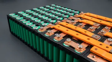
Solar and wind installations use busbars in inverters and combiner boxes to efficiently collect power from multiple sources. EV battery packs employ busbars to connect cell modules, taking advantage of their rigid, thin geometry to minimize space while handling high DC currents. Data centers increasingly deploy busway systems—enclosed bus ducts—for flexible, scalable power distribution to server racks. Overhead busway installations can free approximately 8% of data room white space by eliminating traditional floor-mounted power distribution units.
Busbars vs. Cables: Key Differences and When to Use Each
Choosing between busbars and cables comes down to current levels, routing constraints, and long-term maintenance demands. Here's how each option performs across the factors that matter most in industrial distribution.
Key Advantages of Busbars Over Cables
Busbars deliver higher current capacity per unit cross-sectional area due to superior heat dissipation across the bar's flat surface. For a 1,000 A distribution segment, busduct systems require approximately 32% less copper than equivalent cable installations. The low-profile design conserves space inside enclosures, while structural rigidity eliminates cable tray and conduit complexity. Adding new circuits requires only a bolted connection to the bar's surface—no cable splicing, pulling, or junction boxes.
When Cables Are the Better Choice
Cables outperform busbars in several common scenarios:
- Routing paths are too long or irregular for rigid bars
- Flexibility is needed to handle vibration or equipment movement
- Lower current levels make the busbar cost premium hard to justify
For final connections from a distribution point to individual loads, flexible cables remain the practical choice.
Application Threshold
Industry standards establish a clear transition point: cables are preferred for low-voltage systems up to 600–800 A, while rigid busbars become standard for loads of 1,000 A and above. At these higher currents, parallel cable runs become unwieldy, difficult to maintain, and hard to troubleshoot during faults.
The table below summarizes how these factors compare across common distribution scenarios.
| Comparison Factor | Busbars | Cables |
|---|---|---|
| Current Capacity | Superior (handles 1,000+ A easily) | Limited (parallel runs needed above 800 A) |
| Heat Dissipation | Excellent (large surface area) | Moderate (bundling restricts airflow) |
| Space Usage | Compact (low-profile rigid bars) | Larger (requires cable trays/conduit) |
| Ease of Adding Taps | Simple (bolt to bar surface) | Complex (requires splicing/junction boxes) |
| Installation Cost | Higher material cost, lower labor | Lower material cost, higher labor |
| Flexibility | Low (rigid, fixed paths) | High (routes around obstacles easily) |
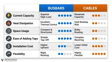
Comparison of busbar and cable systems for industrial power distribution.
Frequently Asked Questions
What is a busbar and how does it work?
A busbar is a rigid metallic bar—typically copper or aluminum—that collects current from a power source and distributes it to multiple circuits through a shared, low-resistance conductor path. Housed inside switchgear or panel enclosures, it provides superior current capacity and heat dissipation compared to equivalent cable runs.
Why use a busbar instead of cables?
Busbars offer higher current-carrying capacity in a compact form, better heat dissipation across flat surfaces, lower installation complexity for multi-circuit distribution, and the ease of adding new taps without splicing. For loads above 1,000 A, busbars eliminate the need for unwieldy parallel cable runs.
How does a 3-phase busbar work?
A three-phase busbar system uses three separate conductor bars—one per phase—running in parallel inside a single enclosure, distributing balanced AC power to multiple loads simultaneously while keeping phases physically separated and insulated.
What is the difference between AC and DC busbars?
AC busbars must account for the skin effect—favoring flat or hollow shapes at 50–60 Hz—and are arranged in multi-phase sets. DC busbars carry constant unidirectional current with no skin effect concerns, making solid cross-sections more practical.
What is a busbar used for?
Busbars distribute electrical power to multiple circuits inside switchgear, motor control centers, power distribution boards, industrial machinery, battery packs, and renewable energy installations. They serve as the backbone conductor wherever high current density and efficient multi-circuit distribution are required.
How many types of busbars are there?
Busbars are classified by system configuration (single, double, ring), by shape (flat rigid, laminated/flexible, round/tubular), and by current type (single-phase AC, three-phase AC, DC).