Introduction
A manufacturing line goes dark mid-shift. A water treatment facility loses pumping capacity. An oil and gas control panel drops offline during a critical operation. In high-stakes industrial environments, these failures carry real consequences — production losses, safety risks, regulatory violations, and damaged equipment. With the right emergency power infrastructure, operations keep running regardless. That continuity often depends on a single device: the automatic transfer switch (ATS).
This guide covers what facility managers, electrical engineers, and system integrators need to know about ATS technology: how it works, the types available, and how to size and maintain one correctly.
Whether you're specifying equipment for a new manufacturing plant, upgrading municipal water infrastructure, or ensuring compliance in an oil and gas facility, the fundamentals here will help you make the right call.
TLDR: Quick-Reference Summary
- An ATS detects primary power failure and automatically transfers the electrical load to a backup generator without human intervention
- It serves two roles: blocking dangerous backfeed into utility lines and keeping critical loads energized during outages
- Three key selection variables: amperage rating, transition type (open, closed, or delayed), and switching mechanism type
- NFPA 110 and the NEC mandate ATS use in most emergency and standby power systems
- Regular testing and inspection, beyond initial installation, ensures the ATS performs when it counts
What Is an Automatic Transfer Switch and Why It Matters
An automatic transfer switch (ATS) is an electromechanical device wired between a utility power source, a backup generator, and the connected electrical load. It monitors the primary source continuously and acts without operator input — detecting an outage, starting the generator, and switching the load within seconds.
No manual intervention. No delay. No dependence on someone being present to notice the failure.
The Backfeeding Hazard
The NEC and NFPA 110 require transfer switches specifically to prevent backfeeding. When a generator is connected to a building without a proper transfer switch, it can push electricity back onto utility lines that workers assume are de-energized. OSHA explicitly warns that this creates a severe risk of electrocution for utility workers, and accident records document fatalities caused by this exact scenario.
Why Automation Matters
An ATS doesn't wait for someone to notice the outage, walk to a panel, and flip a switch — it detects, responds, and transfers within seconds, even at 2 AM or when a facility is unmanned. This is entirely different from a manual changeover or simple interlock.
That speed gap has direct financial and safety consequences. For manufacturing facilities, water treatment plants, and oil and gas operations, even a few minutes of unplanned downtime can mean:
The Industrial Stakes
- Production losses — unplanned downtime costs the manufacturing sector approximately $260,000 per hour
- Regulatory non-compliance
- Equipment damage
- Public safety failures
Specifying the right ATS prevents this cascade — which is why certifications like UL listing, NEMA 4X compliance, and IEEE 519 adherence are non-negotiable criteria for critical industrial sites. ValuAdd's ATS solutions carry these certifications and are selected specifically for demanding environments where failure is not an option.
How an Automatic Transfer Switch Works: The Step-by-Step Process
Monitoring Phase
The ATS controller (typically microprocessor-based) continuously samples incoming utility voltage and frequency — usually many times per second. It compares measured values against preset acceptable thresholds, typically:
- Voltage within ±10% of nominal
- Frequency within ±3 Hz of nominal
Detection and Initiation
When measured values fall outside acceptable limits, the controller waits through a programmed time delay — filtering out momentary sags before acting. Once a genuine failure is confirmed, the ATS sends a start signal to the standby generator. The generator does not start itself; the ATS initiates it.
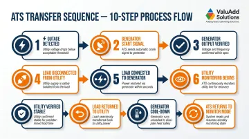
Full Transfer Sequence
- Outage detected by voltage/frequency sensors
- Generator start signal sent by ATS controller
- Generator output verified as stable voltage and frequency
- Load disconnected from utility
- Load connected to generator
- Continuous monitoring for utility restoration
- Utility verified stable for a set time
- Load returned to utility
- Generator runs unloaded for cool-down period
- Generator shuts down and ATS returns to monitoring mode
Key Internal Components
- Microprocessor controller: Executes detection logic, timing delays, and transfer sequencing
- Voltage and frequency sensors: Continuously sample utility and generator output against preset thresholds
- Switching contacts or mechanism: Physically open and close the connections between power sources and load
- Enclosure: Protects internal components from environmental exposure; rated to NEMA standards for the installation environment
The Retransfer Safeguard
The ATS does not immediately switch back to utility when power returns. It waits for the utility to stabilize through a programmable confirmation delay — often 5 to 30 minutes — to prevent nuisance cycling between sources. That cycling damages equipment and accelerates wear on ATS switching contacts.
Types of Automatic Transfer Switches: Mechanisms, Transitions, and Configurations
Switching Mechanism Types
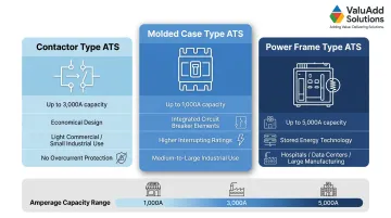
Contactor Type — Up to 3,000 A
Uses electrically controlled, double-throw switches. The most economical option, suited to light commercial and smaller industrial loads. No integral overcurrent protection.
Molded Case Type — Up to 1,000 A
Uses circuit breaker elements as the switching mechanism. Higher interrupting ratings and better short-circuit protection than contactors make this the right choice for medium-to-large commercial facilities and industrial applications with elevated fault current levels.
Power Frame Type — Up to 5,000 A
The highest-capacity option, using stored energy technology for fast, reliable operation. Standard selection for hospitals, data centers, and large manufacturing facilities where any power interruption risks patient safety, data loss, or production shutdown.
Transition Types
Open Transition (Break-Before-Make)
Most common type — breaks the connection to the source being left before completing the connection to the new source, resulting in a brief interruption (typically under one second). This is acceptable for most loads and is the standard selection for general industrial and commercial use.
Closed Transition (Make-Before-Break)
Connects to the new source before disconnecting from the existing source, achieving zero interruption. Synchronization between sources is required, along with utility approval — Con Edison limits this interconnection time to 250 milliseconds, while PG&E caps it at one second.
Essential for sensitive loads, including:
- Variable frequency drives
- Process control systems
- Data-critical equipment
These loads are standard across industrial manufacturing, water treatment, and oil and gas operations.
Delayed Transition
Introduces an intentional time gap between disconnecting one source and connecting the other — allowing residual voltage in inductive loads (motors, transformers) to decay before the new source is applied. Skipping this delay on motor-heavy industrial loads can cause damaging voltage spikes and mechanical shock to driven equipment.
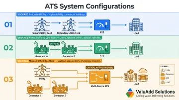
ATS System Configurations
Beyond the standard utility-to-generator setup, common configurations include:
- Utility-utility: Dual utility feeds for facilities with access to two separate utility services
- Generator-generator: For remote off-grid facilities requiring primary and backup generator sources
- Multi-source: Utility + dual generators used in critical infrastructure to ensure backup-to-the-backup coverage
Sizing and Selecting the Right ATS for Your Application
Amperage Sizing
The ATS must be rated to handle the full connected load current without de-rating. When calculating total connected load, account for every circuit that will be served during an outage — not just the largest loads.
Motor inrush current is the critical variable most engineers underestimate. NEC Article 430 requires that conductors and protective devices account for high-current motor start-ups, which can demand six or more times the running current at startup. Size your ATS for inrush, not steady-state running load.
Voltage and Pole Configuration
Single-phase vs. three-phase determines the basic ATS architecture. Industrial three-phase systems (common in manufacturing and water treatment) almost always require 3-pole or 4-pole ATS units.
Pole configurations:
- 2-pole: Single-phase applications
- 3-pole: Three-phase systems with separate neutral
- 4-pole: Three-phase systems requiring a switched neutral (separately derived power systems per NEC 250.30)
A switched neutral is required when the source and load have incompatible grounding schemes — particularly in delta-to-wye configurations or separately derived systems where an unswitched neutral creates a ground fault path.
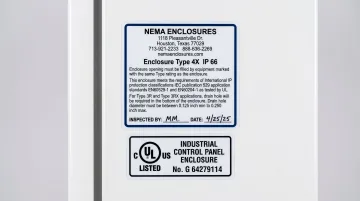
Environmental and Compliance Factors
NEMA enclosure ratings:
- NEMA 12: Indoor industrial environments (protection against falling dirt and dripping water)
- NEMA 4X: Outdoor or washdown environments (protection against windblown dust, rain, hose-directed water, and corrosive agents)
Electrical environment compliance:
- UL 1008: The baseline listing requirement for all ATS equipment — verify this on any unit before specifying
- IEEE 519: Sets harmonic distortion limits at the Point of Common Coupling — 8.0% THD maximum for voltage on systems ≤ 1.0 kV
- Withstand and Closing Ratings (WCR): UL 1008 requires ATS units to withstand and close on specific fault currents until the overcurrent protective device clears the fault
Miss any of these on a permitted installation and you'll face failed inspections, potential liability exposure, and — in water treatment or oil and gas facilities — possible regulatory shutdown.
ATS vs. Manual Transfer Switch: When Each Makes Sense
Core Operational Difference
An ATS monitors, decides, and transfers automatically with no human presence required. A manual transfer switch (MTS) requires a person to physically operate a lever or switch at the panel to move between power sources. Both prevent backfeeding — the difference is response time and whether anyone needs to be on-site when the outage hits.
When a Manual Transfer Switch Is Appropriate
- Portable generator applications where the generator must be manually started anyway
- Non-critical loads where a brief delay is acceptable
- Budget-constrained applications such as supplemental lighting or HVAC backup for a small facility
When an ATS Is Required or Strongly Preferred
- Any standby generator installation governed by NFPA 110 (emergency and legally required standby systems)
- Facilities that are remotely monitored or unmanned
- Operations with life-safety or process-critical loads (medical equipment, fire pumps, wastewater treatment)
- Any application where the cost of downtime exceeds the cost of the ATS
These operational realities align directly with NEC code classifications, which formalize the requirement:
| NEC Article | System Type | Transfer Equipment Requirement |
|---|---|---|
| Article 700 | Emergency Systems | Automatic only |
| Article 701 | Legally Required Standby | Automatic only |
| Article 702 | Optional Standby | Manual or automatic |
ATS Maintenance, Testing, and Common Problems
Testing Frequency Requirements
NFPA 110 requires monthly no-load testing and annual load bank testing%20NFPA%20110%20Testing%20and%20service%20requirements%20for%20Standby%20Power%20Systems_12.15.2020.pdf) for most emergency power systems. Critical facilities like hospitals and water utilities often test weekly.
No-load test: The generator and ATS exercise without actual load. Per Joint Commission standards, the generator must run for at least 30 continuous minutes at a dynamic load of 30% or more of nameplate rating.
Load bank test: A simulated load verifies performance under realistic conditions. Required annually when monthly testing fails to reach the 30% load threshold, this test applies a supplemental load bank for 1.5 to 2 continuous hours.
Most Common ATS Failure Points
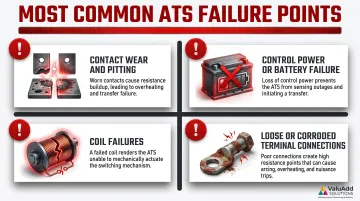
Regular testing surfaces these failure points before they cause a missed transfer:
- Contact wear and pitting: High cycle counts degrade contacts in contactor-type ATS units — inspect for pitting and surface erosion
- Control power supply or battery failure: A dead or degraded battery disables the controller entirely, preventing any automatic response
- Coil failures: Failed coils in the switching mechanism prevent the ATS from completing a transfer
- Loose or corroded terminal connections: These cause intermittent transfer failures or nuisance transfers that are difficult to diagnose under load
Practical Inspection Checklist
Each inspection visit should address the failure points above. Use this checklist to confirm full system readiness:
- Visually inspect contacts and enclosure interior for arc damage, moisture, or corrosion
- Verify control voltage levels are within spec
- Functionally test time delay settings
- Conduct an exercise test to confirm the full transfer and retransfer sequence
- Document test results with date and technician sign-off for NFPA 110 compliance records
Frequently Asked Questions
What is an automatic transfer switch for a generator and how does it work?
An ATS is a device wired between the utility feed, the generator, and the building's electrical system that monitors incoming power and automatically switches the connected load to the generator when utility power fails — then transfers back when utility power is restored.
Can an automatic transfer switch start a generator automatically when the power goes out?
Yes — the ATS sends a start signal to the standby generator upon detecting a power failure; the generator does not start itself. This requires a generator with an electric start and a control interface compatible with the ATS. Portable pull-start generators cannot receive this signal.
How do I size an automatic transfer switch for my generator?
The ATS amperage rating must equal or exceed the total load current it will carry, and it must match the system voltage and phase configuration. A licensed electrician or electrical engineer should perform the load calculation to account for motor inrush and future load growth.
What's the difference between an automatic transfer switch (ATS), a static transfer switch (STS), and an emergency transfer switch?
The three differ primarily by switching speed and application:
- ATS: Uses electromechanical contacts for generator-to-utility transfers; transfer times are measured in seconds
- STS (Static Transfer Switch): Uses solid-state electronics for sub-cycle transfer times of 2-4 milliseconds, suited for UPS and dual-utility applications with ultra-sensitive loads
- Emergency Transfer Switch: Typically an ATS listed and installed specifically for legally required emergency systems under NFPA 110
What are common problems and maintenance/inspection items for an automatic transfer switch panel?
The top failure points are worn or pitted switching contacts, failed control power supply, loose terminal connections, and coil failures. Regular functional testing, visual inspection, and load bank testing per NFPA 110 are the primary maintenance activities.
Is an automatic transfer switch required for commercial and industrial generator installations?
Yes. The NEC (Articles 700, 701, and 702) and NFPA 110 require transfer switching for legally required emergency, legally required standby, and optional standby systems in commercial and industrial facilities. Operating without a transfer switch creates a backfeeding hazard for utility workers and violates code in virtually all jurisdictions.