Introduction
Engineers and installers working on solar PV systems routinely struggle with one source of complexity more than any other: NEC Article 690. As the primary electrical code governing PV system safety in the United States, its disconnecting means and protection requirements carry the highest compliance stakes of any section practitioners will encounter.
The challenge goes beyond knowing individual rules. Practitioners must navigate strict scoping boundaries between Articles 690, 691, and 705, apply compound multipliers for conductor sizing, and adapt to code cycle changes that have relocated and restructured key provisions.
This article breaks down NEC 690's core requirements for disconnecting means, overcurrent protection, arc-fault detection, rapid shutdown, the 120% interconnection rule, and grounding—giving practitioners a focused reference for design and inspection that reflects both 2023 provisions and proposed 2026 changes.
Key Takeaways
- NEC Article 690 covers electrical safety for PV systems under 5,000 kW — arrays, inverters, and interconnections for both stand-alone and grid-tied installations
- Disconnecting means must be readily accessible, marked "PV SYSTEM DISCONNECT," and limited to six switches or breakers per system
- PV conductor sizing applies a 156% combined multiplier: 125% continuous load factor compounded onto 125% conductor ampacity
- Rapid shutdown mandates conductors on buildings drop to 30 V within 30 seconds to protect first responders
- Under the 120% rule, PV backfeed is allowed onto service panel busbars up to 120% of busbar ampacity — provided the breaker is positioned at the opposite end from the main
What NEC Article 690 Covers and Who It Applies To
Article 690 applies to photovoltaic systems including the array, inverters, charge controllers, wiring, disconnecting means, and energy storage. It covers both stand-alone systems and utility-interactive (grid-tied) systems with or without battery backup. Large-scale utility-grade PV power plants rated at 5,000 kW or greater fall under Article 691 rather than Article 690, while interconnection rules for parallel power sources are governed by Article 705.
Why PV Systems Require Specialized Code Provisions
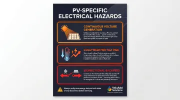
PV systems present unique hazards that distinguish them from conventional electrical installations. Arrays generate voltage continuously whenever light is present; unlike conventional circuits, there is no source-side switch that stops production. Open-circuit voltage (Voc) also rises in cold weather, sometimes exceeding equipment ratings if temperature correction factors aren't applied during design.
Backfeed compounds the risk further, creating shock hazards on both line and load sides of disconnects even when open. This is a condition many electricians trained on conventional AC systems haven't encountered before.
These characteristics demand specialized disconnect construction, precise voltage calculations, and protection schemes that account for continuous generation and bidirectional current flow.
Who This Article Directly Impacts
These requirements directly affect:
- Electrical system integrators designing PV interconnections for commercial and industrial facilities
- Contractors pulling permits and navigating Authority Having Jurisdiction (AHJ) inspections
- Facility managers at manufacturing or processing plants adding rooftop or carport PV
- Engineers specifying components for commercial or industrial solar installations
For all of these roles, misreading disconnect placement, conductor sizing, or marking requirements typically surfaces at inspection — and corrections at that stage are expensive. The sections below break down where Article 690 draws its clearest lines.
NEC 690.13: PV System Disconnecting Means Requirements
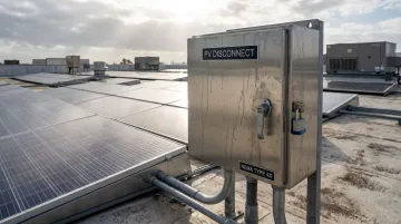
Section 690.13 requires a disconnecting means that simultaneously disconnects all PV system conductors that are not solidly grounded from all conductors of other wiring systems—utility, energy storage, and premises wiring. The disconnect must be permanently marked "PV SYSTEM DISCONNECT" or equivalent. Where line and load terminals may remain energized in the open position, a warning label indicating the electric shock hazard on both sides is required.
In the 2026 NEC, Section 690.13 was significantly reduced and now directs users to Section 705.20 as the unified framework for interconnected source disconnect requirements. This change eliminates duplicative language and creates consistent rules across PV, generators, and energy storage systems.
Disconnect Location and Accessibility Requirements
The "readily accessible" requirement means the disconnect must be reachable without climbing obstacles or using a portable ladder. Section 240.24(A) mandates that the center of the grip of the operating handle be no more than 6 feet 7 inches above the floor or working platform, with a practical mounting range of 4.5 to 6.5 feet. Rooftop-only disconnects and disconnects inside locked rooms fail this requirement and cause frequent inspection failures.
The "within sight" requirement means the disconnect must be visible and not more than 50 feet from the equipment it controls. When within-sight placement is impossible, the disconnect must be capable of being locked in the open position using a lockout device that remains in place whether the lock is installed or removed, per NEC 110.25.
Disconnect Ratings, Number, and Device Types
Device count and type are both regulated under this section. Each PV system may use no more than six switches, six sets of circuit breakers, or a combination of both, mounted in a single enclosure or grouped set of enclosures. This limit applies to a single PV system's disconnecting means—not the total number of PV systems at a service.
Three device selection requirements are critical:
- Disconnect devices for DC PV circuits must carry a DC voltage rating—AC-rated devices do not qualify
- Voltage rating must reflect the temperature-corrected maximum open-circuit voltage per NEC Table 690.7
- Devices must have load-break capability, since DC arcs lack the natural zero-crossings found in AC waveforms and are significantly harder to extinguish
That load-break requirement directly informs component selection. Class E2 Load Break rated devices—such as ValuAdd's INOSYS LBS UL 98B disconnect switches—are designed specifically to interrupt DC load currents safely, meeting the requirements of both NEC 690.13 and 705.20. The INOSYS LBS is rated to 1,500 VDC across a range of 10A to 1,200A configurations, certified to UL 98B and IEC 60947-3, and includes visible contacts with arc fault containment.
Overcurrent Protection, Arc-Fault Detection, and the 120% Rule
PV source circuits, output circuits, and inverter output circuits all require overcurrent protection (fuses or circuit breakers). These devices must be rated at no more than 125% of the maximum circuit current as defined in NEC 690.8.
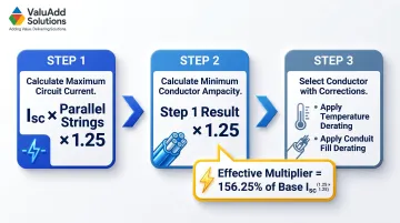
Because PV circuits are continuous loads, conductors must also be rated at 125% of the overcurrent device rating. This produces an effective conductor ampacity multiplier of 156.25% on the module's short-circuit current (Isc).
Standard AC overcurrent devices must never be used for DC circuits. They lack the arc-extinguishing design needed to interrupt DC current safely, even if their AC voltage rating appears adequate. Devices must be specifically listed for DC use, such as UL 489 for molded-case circuit breakers up to 1,500V DC.
Sizing Overcurrent Devices for PV Circuits
The NEC 690.8 calculation follows this sequence:
- Calculate maximum circuit current: Sum of parallel string Isc values × 1.25
- Calculate minimum conductor ampacity: Maximum circuit current × 1.25
- Select conductor: Must have ampacity meeting step 2 after temperature and conduit fill corrections
Example calculation structure:
- Module Isc (from spec sheet): Use actual value
- Strings in parallel: Count from system design
- Maximum circuit current = (Module Isc × strings) × 1.25
- Minimum conductor ampacity = Maximum circuit current × 1.25
- Effective multiplier on base Isc: 1.5625 (156.25%)
When no more than two strings of identical modules are connected in parallel, overcurrent protection may not be required under certain conditions per NEC 690.9. This exception reduces combiner box complexity for small arrays, but requires documentation confirming conditions are met.
Arc-Fault Circuit Interrupter (AFCI) Requirements
NEC 690.11 requires AFCI protection for PV system DC circuits operating at 80V or higher on buildings. The AFCI device must detect arcing faults and de-energize the circuit. Many modern inverters include integral AFCI functionality, eliminating the need for separate devices.
Exemptions apply for:
- PV DC circuits using metal-clad cables or metal raceways
- Underground installations not located in or on buildings
- Systems located on detached structures whose sole purpose is to support PV equipment
Ground-mounted systems using these wiring methods often qualify for exemptions, but inspectors may request documentation proving compliance.
The 120% Rule for Solar Interconnection
Worked example:
- Service panel busbar rating: 200A
- Maximum combined rating: 200A × 1.20 = 240A
- Main service breaker: 200A
- Maximum PV backfed breaker: 240A - 200A = 40A
This rule often allows PV interconnection without replacing the service panel. However, the PV backfed breaker must be positioned at the opposite end of the busbar from the service entrance to comply with the "opposite end rule." This placement distributes current load across the busbar length rather than concentrating it at a single point.
Common permit rejection causes:
- Failing to apply the 125% continuous load multiplier to inverter output
- Incorrect backfed breaker placement on busbar
- Undersized feed-through conductors not rated for combined source current
All three of these rejection causes are avoidable with a completed load calculation sheet submitted alongside the permit application. Reviewers flag the 120% rule more than almost any other provision in commercial PV design, so showing the arithmetic explicitly reduces back-and-forth with the AHJ.
NEC 690.12: Rapid Shutdown Requirements
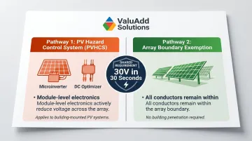
Rapid shutdown requires that PV system circuits installed on or in buildings be capable of reducing conductor voltage to 30V or less and current to 240VA or less within 30 seconds of initiating shutdown. This requirement exists specifically to protect firefighters from electrocution during structure fires.
Voltage reduction boundaries:
- Outside the array boundary: Conductors more than 1 foot from the array must drop to 30V or less
- Inside the building: Conductors more than 3 feet from the building penetration must drop to 30V or less
Compliance Pathways
Two main compliance pathways exist:
- PV Hazard Control System (PVHCS): Uses module-level power electronics (MLPEs) — microinverters or DC optimizers — to actively reduce voltage throughout the array
- Array boundary exemption: Applies to systems where all conductors stay within the array boundary and don't penetrate the building (primarily ground-mounted installations)
Since 2020, MLPE adoption has remained around 90% for small PV systems, while DC optimizers represent 38% of the large nonresidential market, driven largely by rapid shutdown compliance needs.
Marking Requirements
Buildings with PV systems must display:
- Rapid shutdown switch at a clearly visible location (typically near the main electrical service)
- Placard showing the system layout
- Reflective label with white capitalized letters on red background stating "RAPID SHUTDOWN SWITCH FOR SOLAR PV SYSTEM"
The 2023 NEC explicitly exempts PV equipment on non-enclosed detached structures (e.g., parking shade structures, carports, solar trellises) from rapid shutdown requirements, significantly reducing compliance burden for commercial carport installations.
System Design Implications
Rapid shutdown directly shapes inverter and MLPE selection for rooftop systems. Integrators specifying commercial or industrial rooftop PV must confirm shutdown compliance is built into the inverter or MLPE platform before finalizing the disconnect architecture.
Retrofit compliance for older systems can require complete inverter replacement or full MLPE installation — making this one of the costliest NEC provisions to address after initial build-out.
Grounding, Bonding, and Marking Requirements
NEC 690 permits both grounded and ungrounded (functionally grounded) PV systems, but equipment grounding conductors are mandatory in all configurations. Metallic module frames, racking structures, and equipment enclosures must be bonded to maintain electrical continuity and provide a low-impedance fault current path. Ground-fault protection is required to detect faults and de-energize the faulted circuit, with a visual or audible indicator.
Marking Requirements
Per NEC 690.31 labeling requirements, all raceways, junction boxes, pull boxes, and enclosures containing PV conductors must be labeled "WARNING: PHOTOVOLTAIC POWER SOURCE". Labels must be:
- Reflective
- Red background with white text
- Permanent
- Spaced no more than 10 feet apart
PV modules must be marked at the factory with Voc, Isc, maximum system voltage, and maximum power ratings. Section 690.7(D) requires a permanent label indicating the highest maximum DC voltage at the DC disconnect, power conversion equipment, or distribution equipment.
Enclosure Environmental Protection
Outdoor disconnect enclosures for PV systems require weather-rated enclosures suitable for the installation environment. For commercial, industrial, or rooftop applications exposed to moisture and corrosive conditions, NEMA Type 4X-rated enclosures provide the protection level required by NEC 690 and 110.28 for durable, long-service outdoor installations.
ValuAdd offers NEMA Type 4X enclosures suitable for harsh outdoor PV environments, including products with complementary IP65, IP66, and IP68 ratings. These combined ratings provide verified protection against water ingress, dust, and corrosive elements — well-suited for rooftop and ground-mounted installations across industrial sites.
Frequently Asked Questions
What is Article 690 in the NEC?
NEC Article 690 is the section of the National Electrical Code that establishes electrical safety requirements for solar photovoltaic (PV) systems, covering arrays, inverters, wiring, disconnecting means, grounding, and protection for both stand-alone and utility-interactive systems. Large-scale utility plants rated at 5,000 kW or greater are excluded and fall under Article 691.
What is the 120% rule for solar?
The 120% rule (NEC 705.12) permits a PV backfed breaker to connect to a service panel busbar as long as the combined rating of the service breaker and PV breaker does not exceed 120% of the busbar's labeled ampacity. Most panels can accommodate solar without a busbar upgrade, provided the backfed breaker is positioned at the opposite end from the main breaker.
What is rapid shutdown and when is it required under NEC 690?
Rapid shutdown (NEC 690.12) requires PV conductors on or in buildings to reduce to 30V or less within 30 seconds of activation. It is required for rooftop and building-integrated PV systems and is designed to protect firefighters from electrocution hazards during structure fires. Ground-mounted systems and detached structures supporting only PV equipment may qualify for exemptions.
How many disconnects are allowed in a PV system under NEC 690?
NEC 690.13 (via 690.4(C)) allows a maximum of six switches or circuit breakers, or a combination thereof, to serve as the disconnecting means for a single PV system. This six-disconnect limit applies per system, not per service—multiple PV systems at one location can each have up to six disconnects.
Do PV systems require arc-fault circuit interrupter (AFCI) protection?
Yes, NEC 690.11 requires AFCI protection for DC PV circuits operating at 80V or greater on buildings. The AFCI device must detect and interrupt arc faults; many modern inverters include built-in AFCI capability. Ground-mounted systems using metal-clad cables, metal raceways, or underground installations may qualify for an exemption.
What is the difference between the DC and AC disconnect in a solar PV system?
The DC disconnect isolates the PV array's output from the inverter and must be rated for DC voltage (typically 600V–1,000V DC), while the AC disconnect isolates the inverter's output from the premises wiring or utility. DC disconnects require special arc-extinguishing construction because DC current lacks the natural zero-crossing of AC, making interruption considerably more difficult.