Introduction
Most solar system failures trace back not to the panels or inverter, but to undersized or incorrectly specified combiner box internals. An improperly rated fuse blows prematurely under high irradiance. A non-load-break disconnect arcs under DC current. An undersized busbar overheats at its terminals. Each is a distinct failure mode with serious safety and financial consequences.
This article is written for electrical engineers, system integrators, and EPC contractors who need to make informed component-level design decisions rather than selecting a pre-configured box. We'll cover the function and correct specification of PV string fuses, DC disconnects, and busbars, and how these three elements interact to protect utility-scale and commercial solar installations.
TLDR:
- PV string fuses: gPV-rated (IEC 60269-6), sized at 1.56× Isc for DC arc protection
- Class E2 load-break disconnects required — non-load-break switches arc catastrophically under load
- Busbars rated at 125% of total string current; terminal torque is critical
- Cold-weather Voc derating dictates component voltage ratings across all three elements
- NEC 690 permits fuse omission only when string Isc stays within conductor ampacity
What Is a Solar Combiner Box and Why Internal Component Design Matters
A solar combiner box is an electrical enclosure that combines multiple PV string outputs into a single DC feed to the inverter. Per NEC Article 690, a DC combiner is "a device used to combine two or more DC circuit inputs into one DC circuit output."
Contrary to industry folklore, NEC 690 does not mandate combiner boxes based on an arbitrary string-count threshold. The requirement is functional, driven by overcurrent protection, conductor sizing, and equipment isolation needs.
The box itself is simply a container. Its protective value comes entirely from internal component selection:
- An undersized fuse cannot interrupt reverse fault current, leading to cable overheating and fire risk
- Using a non-load-break disconnect under load sustains DC arcing, causing switch failure or explosion
- An undersized busbar creates high-resistance joints that overheat and lead to terminal failure
Core Internal Components
This article focuses on three primary internal design elements:
- PV string fuses — Interrupt reverse current flow from parallel strings during faults
- DC disconnects — Provide safe isolation for maintenance and emergency shutdown
- Busbars — Aggregate string currents and distribute them to the output circuit
Supplementary components like surge protection devices (SPDs) and monitoring systems serve different protective functions and are not covered in depth here.
PV String Fuses: The First Line of Overcurrent Defense
Core Protection Purpose
PV string fuses interrupt reverse current flow when one string develops a fault (short circuit or ground fault) while parallel strings continue to supply current. Without fuses, reverse current from healthy strings can exceed the faulted string's cable ampacity, causing insulation damage and fire risk inside the combiner box.
Why gPV-Rated Fuses Are Required
Standard AC fuses cannot be used in DC PV circuits. DC arcs lack natural zero-crossings, which normally occur 100 or 120 times per second in AC systems and allow arcs to self-extinguish. DC arcs won't self-extinguish without specialized arc-quenching designs.
IEC 60269-6 gPV fuses are specifically designed for DC PV applications up to 1,500 VDC. Key design characteristics include:
- Full-range DC breaking capacity with a minimum 10 kA DC rating
- Ceramic arc chutes and sand-filled chambers to forcibly extinguish DC arcs
- "gPV" utilization category confirming suitability for PV-specific fault conditions
The 1.56× Isc Sizing Rule
The industry-standard 1.56× Isc fuse sizing rule comes directly from NEC 690.8 requirements:
- 690.8(A)(1): Sum the parallel module Isc values, then multiply by 125% to account for irradiance variations
- 690.8(B)(1): Apply a second 125% multiplier when sizing the overcurrent device for continuous load
Applying both: 1.25 × 1.25 = 1.56× Isc minimum fuse rating
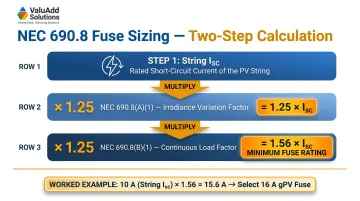
Example Calculation:
- String Isc = 10A
- Minimum fuse rating = 10A × 1.56 = 15.6A
- Select next standard fuse size: 16A gPV fuse
Voltage Rating Requirements
Fuses must be rated for the maximum system DC voltage, which reaches 1,500 VDC in modern utility-scale arrays. NEC 690.7(A) requires calculating maximum DC voltage by correcting the sum of series-connected modules' rated open-circuit voltage (Voc) for the lowest expected ambient temperature.
Cold-weather Voc derating matters: At low ambient temperatures, Voc rises and can exceed the fuse's rated voltage if not properly accounted for. Use manufacturer temperature coefficients or NEC Table 690.7(A) correction factors for crystalline silicon modules.
NEC 690.9 Exception: When Fuses Are NOT Required
NEC 690.9 provides specific exceptions where string fuses may be omitted:
- No external sources (parallel strings, batteries, or inverter backfeed) exist
- The short-circuit currents from all sources do not exceed the ampacity of the conductors AND the maximum overcurrent protective device size rating specified on the PV module nameplate
In practice, this applies to single-string systems or configurations where reverse current cannot occur.
DC Disconnects: Load-Break vs. Non-Load-Break Selection
Disconnect Function and Placement in the Circuit
DC disconnects serve two distinct purposes:
- Safe isolation for maintenance — De-energizing the circuit for servicing
- Fault interruption during overcurrent events — Automatic or manual current interruption
Critical distinction: A disconnect switch (manual isolation) and a DC circuit breaker (automatic fault interruption) are not interchangeable in design. The key specification is whether the device is load-break rated.
Load-Break vs. Non-Load-Break (Isolator) Disconnects
- Load-break disconnect: Can safely interrupt current while load is still connected
- Non-load-break isolator: Must only be operated under no-load conditions
Consequences of using a non-load-break switch under load: Sustained arcing due to the lack of zero-crossing in DC current, which can cause catastrophic switch failure, fire, or explosion.
Class E2 Load-Break Ratings
IEC 60947-3 governs DC switching capabilities. Class E2 designates a disconnect capable of repeated load-break switching cycles (typically 100 operations), making it appropriate for regular maintenance isolation without system de-energization.
The ValuAdd SIRCO MOT DC ESS and INOSYS LBS UL 98B are Class E2 certified for solar combiner applications requiring frequent switching — both rated to 1,500 VDC with breaking capacities of 750 VDC per pole.
NEC 690.15 Equipment Disconnecting Means vs. NEC 690.12 Rapid Shutdown
These serve different code functions:
| Code Section | Function | Requirements |
|---|---|---|
| NEC 690.15 | Isolates specific equipment for servicing | Must be "in sight from" (visible and within 50 ft) and readily accessible or lockable; rooftop DC combiners require a load-break disconnect within 6 ft |
| NEC 690.12 | Reduces shock hazards for emergency responders | Requires controlled conductors inside the array boundary to drop to 80V or less within 30 seconds |
The 6 ft rooftop requirement under 690.15 is a common design oversight. A load-break disconnect at the combiner box satisfies 690.15 equipment isolation but does not inherently satisfy 690.12 unless integrated into a listed PV Hazard Control System (PVHCS).
DC Arc Interruption: MCCB Specification Errors
AC-rated molded case circuit breakers (MCCBs) cannot be assumed to handle equivalent DC voltages — and this is one of the most frequent specification errors in combiner box design. UL 489 covers devices rated up to 1,000 Vac and 1,500 Vdc, but DC voltage ratings are routinely far lower than the AC rating on the nameplate.
Example: An ABB XT2 MCCB is rated for 600 Vac, but achieving a 500 Vdc rating requires two or three poles wired in series depending on the required interrupting capacity. This is because:
- DC current lacks the natural zero-crossing that extinguishes AC arcs
- DC-rated breakers use magnetic blow-out arc quenching to forcibly collapse the arc — a mechanism absent in standard thermal-magnetic AC designs
- Series pole configurations extend the effective voltage rating across multiple arc-quench chambers
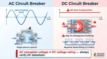
A breaker marked 600V AC may carry a 250V DC rating or less. Always pull the DC-specific datasheet — the AC nameplate voltage is not a safe proxy.
Busbars and Terminal Assemblies: Sizing and Current Capacity
Busbar Role and Configuration
The busbar is the conductive backbone of the combiner box—a metal conductor bar (positive and negative) to which all string inputs are landed, combining current before it exits through the output disconnect or breaker.
Two types of busbars:
- Positive/Negative busbars: Carry full combined string current
- Ground/PE busbar: Serves protective earth bonding only
Copper vs. Tin-Plated Copper vs. Aluminum Busbars
Tin-plated copper is the dominant choice in combiner box design:
- Lower contact resistance than bare copper
- Superior corrosion resistance in outdoor environments
- Better torque retention at connection points
Aluminum busbars:
- Cost advantage over copper
- Require derating for equivalent current capacity
- Aluminum-to-copper connections require anti-oxidation compound to prevent galvanic corrosion
Busbar Sizing: 125% Ampacity Margin
Per NEC 690.8(B)(1), the busbar must be sized for the total combined output current of all strings, with a minimum 125% safety margin before applying adjustment and correction factors.
Example Calculation:
- 8 strings × 10A Isc = 80A combined current
- Minimum busbar ampacity = 80A × 1.25 = 100A continuous rating
Connection Integrity Requirements
Terminal torque specifications must be followed precisely. Getting this wrong in either direction creates real failure risk:
- Under-torquing creates high-resistance joints that overheat and eventually fail
- Over-torquing cracks busbar terminals or strips threads entirely
Both failure modes are avoidable with proper tooling and torque verification during installation. Best practices for maintaining connection integrity include:
- Use anti-oxidant paste on aluminum conductors
- Specify spring-loaded terminal blocks to maintain connection integrity over thermal cycling in outdoor combiner boxes
- ValuAdd's SB1-SB2 busbar supports use M8 screw connections tested for short-circuit reliability per IEC 61439-1 and IEC 60865-1, and their IEC-certified rigid copper bars are available in 44 configurations—heights from 20–160mm, thicknesses from 5–10mm, and lengths from 1,750–5,800mm—to match most combiner box layouts
How Fuses, Disconnects, and Busbars Interact in the Circuit
Current Path in a Properly Designed Combiner Box
- String current enters through individual fused inputs
- Current lands on the positive/negative busbars
- Combined current flows through the output disconnect/breaker
- Current exits to the inverter
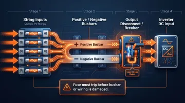
Critical coordination requirement: Each component's rating must be coordinated:
- The fuse must trip before the busbar or wiring is damaged
- The disconnect must safely interrupt the busbar's full aggregate current
Protective Coordination (Selectivity)
The string fuses must blow selectively—a fault on one string should only blow that string's fuse, not the main output breaker. This requires that string fuse ratings be significantly lower than the main output breaker rating.
IEC 60269 Annex BB provides guidance on coordination for PV strings and arrays, outlining how gPV fuse-links should be coordinated within the DC installation.
SPD Integration into the Circuit Architecture
Busbar voltage ratings also determine how SPDs are applied in the circuit. SPDs connect across the positive and negative busbars to ground, and their maximum continuous operating voltage (Uc) must exceed the system's maximum open-circuit voltage (Voc), calculated at cold-weather conditions.
IEC 61643-31 governs SPDs for DC PV installations up to 1,500 Vdc. For example, DEHN offers Type 2 SPDs with Uc ratings of 1,170V for 1,000 Vdc systems and 1,500V for 1,500 Vdc systems.
Accurate Voc calculations are therefore a prerequisite for safe SPD selection, not just a current-capacity consideration.
Sizing, Standards, and Enclosure Compliance
Key US and International Standards
| Component/System | Governing Standard | Scope |
|---|---|---|
| Overall PV System Design | NEC Article 690 (NFPA 70) | Safe electrical design, installation, and inspection of PV systems |
| PV String Fuses | IEC 60269-6 | gPV fuse-links for PV strings up to 1,500 Vdc |
| DC Disconnects & Switches | IEC 60947-3 | Switches, disconnectors, and fuse-combination units |
| Molded Case Circuit Breakers | UL 489 | MCCBs rated up to 1,000 Vac and 1,500 Vdc |
| Surge Protective Devices (SPDs) | IEC 61643-31 | SPDs for DC PV installations up to 1,500 Vdc |
UL Listed components are required for code compliance on all US projects. Enclosure selection is equally non-negotiable — the right NEMA or IP rating must match the physical site environment.
Enclosure Rating Requirements
NEMA 4X enclosures are required for most US outdoor installations, providing:
- Protection against rain and windblown dust
- Corrosion resistance for coastal environments
- UV resistance for high-sun locations
Select enclosure IP and NEMA ratings based on site conditions:
- Coastal installs need stainless steel or fiberglass for corrosion resistance
- Dusty desert sites need sealed gaskets and cable glands to maintain ingress protection
- High-UV locations need UV-stabilized plastics or powder-coated metal enclosures
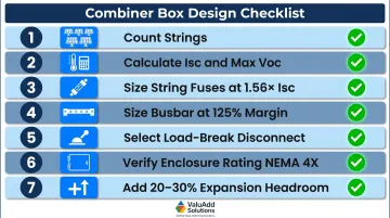
Design Checklist: Key Sizing Steps
- Count strings and determine maximum system configuration
- Calculate Isc and max Voc (temperature-adjusted per NEC 690.7(A))
- Size string fuses at 1.56× Isc using gPV-rated fuses per IEC 60269-6
- Size busbar for total combined current with 125% margin (sum of all string Isc × 1.25)
- Select a load-break rated disconnect for the full output current and system DC voltage
- Verify enclosure rating matches site environment (NEMA 4X for outdoor US installations)
- Add headroom for future expansion (typically 20-30% additional input circuits)
Frequently Asked Questions
How to size a solar combiner box?
Sizing starts with counting PV strings, then calculating maximum string current (Isc) and voltage (temperature-adjusted Voc). Size string fuses at 1.56× Isc, size the busbar and output disconnect for the total combined current with 125% margin, and select a box with enough input circuits plus headroom for future expansion.
How does a solar combiner box work?
The combiner box collects DC current from each solar string through individually fused inputs, combines them on a busbar into a single output, and routes that output through a disconnect or circuit breaker to the inverter. SPDs protect against voltage surges by shunting transients to ground.
How to connect a PV combiner box?
Land each string's positive and negative conductors on the corresponding fused input terminals, then connect the output terminals to the inverter's DC input. All conductors must be sized per NEC 690 ampacity rules, with DC and AC circuits kept separated per code.
Can you connect 100W and 200W solar panels together?
Mismatched panels must go into separate strings — series strings require identical panels to avoid current mismatch losses. Different-wattage strings can share a combiner box as long as each string has its own correctly rated fuse and the box accommodates each string's voltage and current.
What is the difference between a fuse and a circuit breaker in a solar combiner box?
String fuses are single-use devices — compact, DC-rated, and suited for per-string overcurrent protection, but must be replaced after tripping. DC circuit breakers are resettable and typically serve the combiner box output for load interruption and disconnect functions.
What size busbar is needed for a solar combiner box?
The busbar must be sized for the total combined string current (sum of all string Isc values) with a minimum 125% ampacity margin per NEC 690 rules. For example, eight strings at 10A Isc each require a busbar rated for at least 100A continuous.