Introduction
Sizing a solar DC disconnect switch is technically demanding because it involves precise NEC 690 calculations, not just picking an off-the-shelf component. A correctly sized disconnect must account for cold-weather voltage spikes, irradiance-driven current surges, continuous-load derating, and module manufacturer limits—all simultaneously. Errors result in failed inspections, fire risk, or voided warranties.
Licensed electricians, solar PV installers, and system integrators are the intended audience for this guide. DIY sizing without code knowledge creates liability exposure and safety hazards that no AHJ will approve.
This guide covers the complete NEC 690-compliant sizing process, from datasheet to inspection. You'll find:
- Exact voltage and current formulas with NEC 690 multipliers
- Real-world temperature and irradiance corrections
- Equipment specification requirements for switch selection
- Inspection checkpoints that satisfy your local AHJ
Key Takeaways
- Size DC disconnects to at least 125% of total array short-circuit current (Isc) per NEC 690.8
- Voltage rating must exceed cold-weather open-circuit voltage (Voc), not just STC values
- Disconnect must be within sight of the inverter and accessible without tools (NEC 690.13)
- AC-rated switches on DC circuits cause permit rejection and fire hazards
- Always check the module datasheet — its max series fuse rating caps your OCPD selection
What NEC Article 690 Requires for Solar DC Disconnects
NEC Article 690 is the primary federal code governing photovoltaic system disconnects. Three subsections control every sizing and placement decision you'll make:
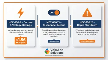
- NEC 690.8 (Current and Voltage Ratings): Calculate maximum circuit current at 125% of parallel module short-circuit currents, then size conductors and overcurrent devices at an additional 125% for continuous loads — a combined 1.56x multiplier.
- NEC 690.13 (Disconnect Means): Each PV disconnecting means must be readily accessible, limited to no more than six switches or circuit breakers, and capable of simultaneously disconnecting all ungrounded conductors.
- NEC 690.12 (Rapid Shutdown): Requires labeling at service equipment locations identifying where the rapid shutdown initiation device is located, along with a simple roof diagram.
Physical Placement and Accessibility Requirements
NEC 690.13 imposes strict location rules. The disconnect must be within sight of and accessible to the inverter—defined by Article 100 as visible and not more than 50 feet distant. The operating handle center grip cannot exceed 6 feet 7 inches (2.0 meters) above the finished grade or working platform.
NEC 110.26 requires a minimum working space width of 30 inches (or the width of the equipment) and at least 3 feet of clear depth in front of the disconnect. No storage, conduit, or other obstructions are permitted in this zone.
The "2 to 6 Disconnect Rule"
NEC 690.13(C) limits the disconnecting means for each PV system to not more than six switches or six sets of circuit breakers. This ensures emergency responders can de-energize the system with a maximum of six hand operations.
In multi-array or multi-inverter commercial layouts, each disconnect counts toward that six-operation limit. If your design requires seven or more separate disconnects, consolidate combiners or install a single main disconnect ahead of the array to stay compliant.
How to Size a Solar DC Disconnect Switch per NEC 690.8
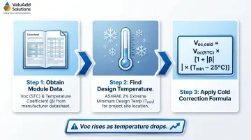
Sizing starts with two values from the module datasheet: short-circuit current (Isc) and open-circuit voltage (Voc at Standard Test Conditions). Isc represents the maximum current the module produces when its output terminals are short-circuited under full sun. Voc is the maximum voltage across the module terminals when no load is connected.
STC values are measured at 25°C cell temperature, 1000 W/m² irradiance, and Air Mass 1.5 spectrum. Real-world conditions—especially temperature extremes—cause these values to shift significantly, which is exactly why NEC 690.8 requires applying correction factors before selecting a disconnect rating.
Step-by-Step Current Sizing Formula
NEC 690.8(A)(1)(a)(1) requires:
Array Maximum Current = (Number of parallel strings) × Isc
Minimum disconnect current rating = 1.25 × Array Maximum Current
The 125% factor accounts for momentary irradiance spikes above 1000 W/m² (which occur during edge-of-cloud events and ground reflection) and the continuous-load nature of PV systems. According to NEC 690.8 requirements, PV systems are classified as continuous loads because maximum current is expected to continue for three hours or more.
If your disconnect or OCPD is not listed for 100% continuous operation, apply an additional 125% multiplier: 1.25 × 1.25 = 1.5625, typically rounded to a 1.56× total factor.
Cold-Weather Voc Correction
Voc rises as temperature drops. Module manufacturers provide a temperature coefficient of Voc (typically expressed as %/°C or V/°C). NEC 690.7(A) requires calculating maximum PV system voltage by correcting Voc for the lowest expected ambient temperature.
Formula:
Voc,cold = Voc(STC) × [1 + |temp coefficient of Voc| × (minimum site temp − 25°C)]
Note: The temperature coefficient of Voc is negative (Voc decreases as temperature rises), so use its absolute value when the site temperature is below 25°C. This ensures Voc,cold is correctly calculated as higher than Voc(STC) at cold temperatures.
Multiply this corrected Voc by the number of modules in series to get total string voltage.
Use ASHRAE 2% extreme annual design temperatures for your location, not the coldest day on record. ASHRAE climatic data provides these values by zip code.
Ignoring this correction is the most common cause of undersized disconnects failing under real conditions.
Temperature Derating for the Disconnect Switch
PV disconnects installed outdoors frequently exceed standard test temperatures. If your disconnect will operate in an ambient temperature above 40°C (104°F), you must apply a derating factor to its current rating.
Example: A disconnect rated 200A at 40°C might require derating to 80% of rated current (160A usable) at 60°C ambient. Check the manufacturer's datasheet for the specific derating curve—some industrial switches claim no derating required even beyond 60°C.
Final Sizing Rule
Select the next standard switch rating above your calculated minimums, then verify it does not exceed the module manufacturer's maximum series fuse rating (shown on the datasheet). This value is a hard upper limit under UL 1703 and UL 61730 testing—per NEC 110.3(B), you cannot exceed it regardless of what your calculations suggest.
Worked Sizing Example: 20-String Commercial PV Array
Array Configuration:
- 20 parallel strings
- 30 modules per string (series-connected)
- Module Voc = 28.4 V
- Module Isc = 7.92 A
- Module Voc temperature coefficient = -0.29%/°C
- Minimum site temperature = -10°C (ASHRAE 2% design temp)
- Ambient operating temperature = 60°C
- Module maximum series fuse rating = 25A
Step 1: Calculate Cold-Weather Voc per Module
The temperature difference from STC is |(-10) − 25| = 35°C. Because the site temperature is below 25°C, Voc increases—use the absolute value of the coefficient:
Voc,cold = 28.4 V × [1 + 0.0029 × 35]
Voc,cold = 28.4 V × 1.1015 = 31.3 V per module
Step 2: Calculate Total String Voc
Total string Voc,cold = 31.3 V × 30 modules = 939 V
The next standard DC voltage rating above 939 V is 1000 VDC — select a switch rated at minimum 1000 VDC.
Step 3: Calculate Array Maximum Current
Array Maximum Current = 20 strings × 7.92 A = 158.4 A
Step 4: Apply NEC 690.8 125% Continuous Factor
Minimum current rating = 1.25 × 158.4 A = 198 A
Step 5: Apply Temperature Derating
If the switch is derated to 80% at 60°C:
Required rated current = 198 A ÷ 0.80 = 247.5 A
Select a switch rated at least 250A at 40°C (which provides ~200A usable capacity at 60°C).
Step 6: Verify Module Maximum Series Fuse Rating
Module limit = 25A. Each string carries 7.92A × 1.25 = 9.9A maximum. This is well below the 25A limit, so no conflict exists.
Summary Sizing Table
| Parameter | Value |
|---|---|
| Module Voc (STC) | 28.4 V |
| Module Isc (STC) | 7.92 A |
| Voc,cold per module | 31.3 V |
| Total string Voc,cold | 939 V |
| Array maximum current | 158.4 A |
| NEC 690.8 minimum current | 198 A |
| Derated current (60°C, 0.80 factor) | 247.5 A |
| Selected voltage rating | ≥1000 VDC |
| Selected current rating | ≥250A |
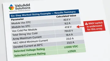
A 600V switch is undersized for this array: cold-corrected string voltage reaches 939V, which exceeds the 600V rating before any safety margin is applied. The 1000V rating is the correct selection.
Selecting and Installing the Right DC Disconnect
Before purchasing, verify these specifications:
- Rated for DC (Not AC): AC and DC arc interruption are fundamentally different. DC current lacks the natural zero-crossing that extinguishes AC arcs, so the switch must be explicitly DC-rated.
- UL 98B or IEC 60947-3 DC-PV2 Listed: These standards test for severe PV array duty, including rapid arc extinguishing under load. Don't accept a switch rated only for AC applications.
- Load-Break Rated: The switch must interrupt live PV circuits at full DC voltage. Isolation-only (non-load-break) switches are not safe for this purpose.
- Correct Enclosure Rating: Outdoor installs require NEMA 3R minimum. Corrosive or marine environments need NEMA 4X. NEC 110.28 mandates NEMA Type ratings. IP ratings like IP65 don't substitute — they don't address corrosion, icing, or construction requirements.
- 2-Pole for Ungrounded Systems: Ungrounded PV systems require simultaneous interruption of both positive and negative conductors. Single-pole switches are insufficient.
Switches meeting UL 98B, NEMA 4X, and Class E2 Load Break requirements — including options available through ValuAdd — arrive pre-certified to NEC 690 standards, which significantly reduces AHJ rejection risk on inspection.
Installation Sequence
- Mount the enclosure per NEC 690.13 clearances: within sight of inverter, handle ≤6.5 feet above grade, minimum 3 feet clear working space
- Land conductors with correct torque specs from manufacturer datasheet
- Verify polarity labeling on terminals and confirm correct conductor routing
- Confirm lockout/tagout capability if required by facility safety procedures
- Affix required NEC labels:
- System voltage (NEC 690.7(D))
- Maximum current
- Rapid shutdown initiation point (NEC 690.12(D))
- PV System Disconnect identification (NEC 690.13(B))
Fused vs. Non-Fused Disconnects
A fused disconnect is needed when the available circuit current from the array can exceed the rated current of any single module or conductor. This applies when you have more than two parallel strings.
Example: If a single module can safely handle 25A (its maximum series fuse rating) but your array has 10 parallel strings each producing 8A, the total available fault current is 80A—well above the module's rating. Fuses sized at or below 25A protect each string from reverse-current damage during partial shading or ground faults.
Common DC Disconnect Sizing Mistakes That Fail Inspections
Using STC Voc Without Cold-Temperature Correction
A common field error: selecting a 600V disconnect for a string array with a nominal Voc of 560V STC, then failing inspection when the cold-weather voltage rise pushes the system over that rating. The root cause is using the module's STC Voc without applying the temperature coefficient correction.
Calculate Voc,cold at the lowest expected site temperature using ASHRAE 2% design data. Select a disconnect rated above that corrected value — most sites with this scenario require stepping up to a 1000V device.
Applying Only One 125% Factor Instead of Two
Sizing a disconnect to exactly 125% of Isc sounds correct — until the device operates at or near its thermal limit and starts nuisance tripping or overheating. The confusion comes from assuming every disconnect is rated for 100% continuous current. Many are only rated at 80%, which demands a second 125% multiplier.
Check the continuous current rating in the product datasheet before finalizing your selection. If the device is an 80%-rated type, apply the additional multiplier — the combined result is a 1.56x factor applied to your string Isc.
Using an AC-Rated or Non-Listed Switch for DC Circuits
Installing an AC-rated disconnect on the DC side is a fire hazard, not just an inspection failure. AC switches cannot safely suppress DC arcs — DC arcs don't self-extinguish at zero crossings the way AC arcs do, so they require magnetic blowouts and larger contact gaps that standard AC switches simply lack.
This mistake typically happens when sourcing from general electrical supply without confirming DC PV listing. Verify the following before purchasing:
- Disconnect is explicitly listed for DC PV service
- Product carries UL 98B listing or IEC DC-PV2 utilization category
- DC voltage rating appears on the device nameplate (not inferred from AC rating)
Pro Tips for NEC 690 Compliance
Avoid the most common plan-check failures and field hazards by keeping these practical guidelines in mind:
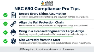
- Record every sizing assumption — module Isc and Voc values, temperature correction factors, ambient derating, and final selected ratings. AHJs now require this calculation worksheet as part of plan review.
- Align the full protection chain — the disconnect's current rating must match upstream string fuse ratings and the inverter's maximum DC input current. A mismatch allows faults to propagate past the intended protection point.
- Bring in a licensed electrical engineer for large commercial or utility-scale arrays with multiple combiner boxes, storage-coupled DC systems, or 1500 VDC operation. These require protection coordination beyond standard residential scope.
- Size correctly from the start — an undersized or non-compliant disconnect doesn't just fail inspection. It can cause fires, void manufacturer warranties, and create liability exposure for the installer.
Frequently Asked Questions
How to choose a solar panel disconnect switch?
Select a DC-rated switch with voltage rating ≥ Voc,cold of the array, current rating ≥ 125% of total array Isc (with additional derating if ambient temperature exceeds 40°C), UL 98B listing for DC PV service, and NEMA 3R minimum (or NEMA 4X for corrosive environments).
What is the NEC code for solar disconnect?
NEC Article 690 governs solar disconnects. Key sections include 690.8 for current and voltage sizing requirements, 690.13 for disconnect placement and accessibility (within sight of inverter, ≤6 operations to de-energize), and 690.12 for rapid shutdown labeling.
What is the 33% rule in solar panels?
Under NEC, PV systems are continuous loads, so all conductors and devices must be rated for at least 125% of calculated current. That means equipment may only be loaded to 80% of its rating during continuous operation. The "33% rule" is informal shorthand for this 125% multiplier.
What is the 2 to 6 disconnect rule?
NEC 690.13(C) allows up to six individual switching operations to fully disconnect all power sources in a PV system. This matters in commercial arrays with multiple inverters or combiners, where each disconnect counts toward the six-operation limit.
Does the solar DC disconnect need to be within sight of the inverter?
Yes. Per NEC 690.13, the DC disconnect must be within sight of the inverter—visible and no more than 50 feet away. The operating handle must be no higher than 6 feet 7 inches above finished grade, with at least 3 feet of clear working space in front.
Can I use an AC-rated disconnect switch on the DC side of my solar system?
No. DC current does not naturally cross zero like AC current, making arc interruption fundamentally different. AC-rated switches cannot safely suppress DC arcs and create serious fire and safety hazards. Only use DC PV-listed switches (UL 98B or IEC DC-PV2 rated).