Introduction
A solar DC disconnect switch installation lives or dies on three factors: correct sizing, proper placement, and full NEC compliance. Get any one wrong and the system either fails inspection or creates a safety hazard that worsens over time.
Undersized or mis-rated switches create arc flash risk. Incorrectly placed disconnects fail NEC Article 690 accessibility requirements. Missing labels are among the most common reasons solar inspections fail.
This guide walks through the full installation process—component selection, conduit routing, termination, and labeling—following NEC Article 690 requirements.
This work should be carried out by licensed electricians or qualified PV system integrators. DIY installation without that background typically results in failed inspections, arc hazards, or code violations. The consequences are real: arc flash incidents, thermal failures at terminals, and systems that stay energized when they need to be isolated for maintenance or emergency response.
Key Takeaways
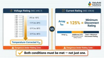
- Size the disconnect to ≥125% of Isc and rate it for temperature-corrected Voc per NEC 690.8 and 690.7
- Mount the handle 4.5–6.5 ft above grade, within sight of the inverter, lockable in open position (NEC 690.13, 690.14)
- Use only DC-rated, load-break switches with appropriate voltage (typically 1000VDC); never substitute AC-rated switches
- Proper labeling, grounding to equipment grounding system, and torqued terminal connections are mandatory code requirements
- Before energizing, confirm with visual inspection, contact resistance measurement, and a no-load switching test
Installation Guide for a Solar DC Disconnect Switch
A DC disconnect installation follows a defined sequence: site/compliance preparation → component selection → physical mounting → wiring and grounding → labeling → validation. Skipping or shortcutting any phase compounds risk in later phases.
Expect to spend 2–4 hours for a single residential disconnect — assuming you've reviewed NEC Article 690 and the manufacturer's datasheet beforehand. Commercial multi-disconnect installations require substantially more coordination.
Prerequisites and Safety Considerations
Sizing and Specification Requirements
Before any physical work begins, confirm these NEC compliance prerequisites:
- Voltage rating: The disconnect must carry a DC voltage rating equal to or greater than the temperature-corrected array Voc. Use NEC Table 690.7(A) correction factors for the site's minimum ambient temperature (e.g., 1.12 multiplier for -1°C to -5°C, up to 1.25 for -36°C to -40°C)
- Current rating: Must meet or exceed 125% of array Isc per NEC 690.8
- Using a 600VDC switch on a system whose corrected Voc exceeds 600V is a dangerous specification error — not a minor one
Site Readiness Requirements
Confirm all three site conditions before mounting:
- Structural fastening: Lag screws into studs or rated concrete anchors — no hollow-wall anchors
- Handle height: Operating handle center must fall between 4.5 and 6.5 ft above finished floor or grade per NEC "readily accessible" requirements
- Working clearance: Minimum 36 in. wide × 30 in. deep clear space in front of the enclosure per NEC 110.26
Non-Negotiable Device Requirements
The switch must be:
- DC-rated for the application — AC interrupting mechanisms are not interchangeable with DC designs
- Load-break capable of interrupting current under normal operating conditions
- Enclosed to NEMA 4X or IP65/IP66 minimum for any outdoor installation
Safety Before Starting
- De-energize the array side as much as possible (cover panels or work during low-irradiance conditions)
- Wear arc-rated PPE including insulated gloves and face shield
- Have a second person present
- Critical: Even a covered or shaded array retains dangerous voltage levels and should never be treated as fully de-energized
With prerequisites confirmed, gather the tools and components before any physical work begins.
Tools and Parts Required
Essential Tools:
- Calibrated torque screwdriver or wrench (with manufacturer torque specifications on hand)
- Digital low-resistance ohmmeter (four-wire Kelvin connection for contact resistance testing)
- Multimeter rated for DC voltage at system levels
- Wire stripper, conduit fittings, appropriate conductor lugs
- Bonding bushings for metallic conduit entries
Component Requirements:
- DC-rated load-break disconnect switch with matching voltage and current rating — UL Listed devices such as those available through ValuAdd's industrial electrical portfolio (including Class E2 load break, NEMA 4X, IP65/IP66-rated options) help ensure NEC compliance and reduce inspection risk
- NEMA 4X or appropriate outdoor enclosure if not integral
- Equipment grounding conductor sized per NEC Table 250.122
- Antioxidant compound for aluminum conductors
No substitutes are acceptable for DC-rated components. An AC-rated switch with a higher nominal voltage number is not interchangeable because arc-interruption mechanisms, insulation clearances, and contact gap designs are fundamentally different.
Once components are staged and tools confirmed, proceed through the installation steps in order.
How to Install a Solar DC Disconnect Switch (Step-by-Step)
Installation follows a strict sequence. Out-of-sequence shortcuts — such as wiring before confirming mounting height compliance or skipping grounding conductor installation — regularly cause rework and failed inspections. Work through each step completely before advancing.
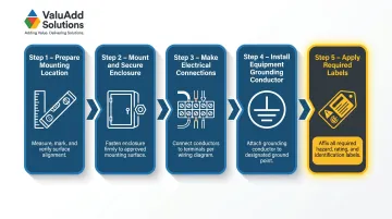
Step 1 — Prepare the mounting location
- Mark and verify the mounting height so the handle center will fall between 4.5 and 6.5 ft above grade
- Confirm clear working space of 36 in. × 30 in. is unobstructed
- For outdoor locations, orient the enclosure on a north- or east-facing wall where feasible to reduce direct sun heating
- Drill and install structural fasteners (lag screws into studs or appropriately rated masonry anchors)
Step 2 — Mount and secure the enclosure
- Attach the enclosure to fasteners and confirm it is level and immovable when the operating handle is cycled
- Check that conduit entry knockouts align with the planned conduit run without creating sharp bends
- Install conduit fittings and bonding bushings at all metallic conduit entries before pulling conductors
Step 3 — Make electrical connections
- Strip conductors to the exact length shown by the terminal strip gauge
- Install conductors into line-side and load-side terminals in the correct polarity
- Apply antioxidant compound to aluminum conductors before insertion
- Tighten all terminals to the torque values printed on the disconnect label or manufacturer datasheet (typically 25–35 lb-in for smaller terminals, higher for larger). Under- or over-torqued connections are a leading cause of thermal failure — use a calibrated tool
Step 4 — Install the equipment grounding conductor
- Connect the grounding conductor to the dedicated green grounding lug or screw inside the enclosure (never to a neutral busbar or mounting screw)
- Size the conductor per NEC Table 250.122
- Ensure bonding bushings on metallic conduit are properly connected to provide a continuous low-impedance fault current path
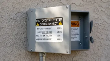
Step 5 — Apply all required labels before closing the enclosure
- Install a permanent, reflective "SOLAR DC DISCONNECT" identification label visible from the operating position
- Install the NEC-required warning label inside the enclosure stating that both line and load terminals may remain energized when the switch is open
- If using a non-load-break isolator (not recommended for most field applications), add a "DO NOT OPEN UNDER LOAD" label directly at the handle
- If the system has multiple disconnects, install a system directory at the utility service disconnect location identifying all disconnect types and locations
Post-Installation Checks and Validation
Visual Inspection Checklist Before Energizing:
- Confirm enclosure gaskets are fully seated and conduit entries are sealed
- Verify all terminal connections are torqued with no exposed conductors beyond the terminal
- Check that all required labels are present and securely attached
- Confirm clear working space remains unobstructed
Inspectors frequently fail installations on label and clearance violations alone.
Functional Testing Before Full Operation:
With the system still isolated on the array side:
- Measure contact resistance across each pole using a four-wire low-resistance ohmmeter — properly functioning contacts read below 1 milliohm
- Cycle the operating handle several times without load to confirm smooth mechanical operation and consistent detent engagement
- Verify with a DC-rated multimeter that the switch fully isolates voltage on the load side when open
Indicators of Correct vs. Incorrect Installation:
✅ Correct: Smooth handle operation, sub-1 milliohm contact resistance, no visible discoloration or exposed conductors, all labels in place, enclosure fully sealed
❌ Incorrect: Binding handle, elevated contact resistance, terminals showing scorch marks, missing or paper labels, enclosure gasket not seated
A system that passes all three functional tests before energization is ready for AHJ inspection — one that doesn't is far cheaper to correct now than after a thermal event in the field.
Common Installation Problems and Fixes
These are the most frequently encountered issues during or immediately after installation, often discovered at inspection or during initial operation.
Incorrect Voltage Rating (AC-Rated Switch Used in DC Application)
Problem: System voltage appears within the switch's marked rating, but the switch is rated for AC operation only, with no DC voltage marking on the nameplate.
Likely cause: Specification error or procurement shortcut—the installer selected a switch based on nominal voltage number without verifying the DC-specific rating. AC and DC interrupting mechanisms are not interchangeable regardless of matching voltage figures.
Fix: Replace with a switch that carries an explicit DC voltage rating on the nameplate equal to or greater than the temperature-corrected array Voc. Verify the DC rating specifically, not the AC rating.
Switch Mounted Too High (Fails "Readily Accessible" Requirement)
Problem: Disconnect handle is positioned above 6.5 feet, requiring a stepladder to operate. Installation fails NEC 690.13 "readily accessible" definition at inspection.
This typically happens when installers prioritize tamper prevention or equipment clearance over the NEC accessibility standard—common in commercial high-traffic areas.
Remount the enclosure so the handle center falls between 4.5 and 6.5 feet above grade. For tamper resistance, use a lockable disconnect with a padlock provision rather than mounting out of reach.
Missing or Deteriorated Labels
Problem: Identification and warning labels are absent, handwritten on tape, or printed on non-UV-resistant materials that have faded or peeled. Installation fails inspection or leaves the disconnect inadequately marked for maintenance and emergency use.
Likely cause: Labels treated as an afterthought rather than a code requirement; use of non-durable label stock in outdoor environments.
Fix: Replace all labels with pre-printed, reflective, UV-resistant labels rated for outdoor service. Check each of the following before proceeding to commissioning:
- Identification label is visible from the operating position without opening the enclosure
- Energized-terminal warning label is visible when the enclosure is opened
- No handwritten, faded, or tape-applied labels remain anywhere on the enclosure
Pro Tips for Installing a Solar DC Disconnect Switch Effectively
Sequencing tip: Complete all labeling before the final enclosure closure and before the system inspection. Label corrections after a failed inspection require a re-inspection visit and delay project completion. Treat labeling as a parallel task to wiring, not an afterthought.
Component sourcing and specification tip: Source DC disconnect switches from suppliers who provide technical documentation, UL Listing, and explicit DC voltage ratings — suppliers like ValuAdd carry Class E2 load break, NEMA 4X-rated components built to these requirements. This prevents mis-rated devices from reaching inspection. Confirm the nameplate shows a DC voltage rating before reviewing any other specification.
Documentation best practice: Photograph each installation stage and record terminal torque values. This documentation supports inspection sign-off and provides a baseline for future maintenance contact resistance comparisons. Key photos to capture:
- Mounting height with a tape measure visible
- Terminal connections before closing the enclosure
- All labels in place and legible
When to involve a specialist: If the system involves multiple inverters, DC string voltages exceeding 1000VDC, or installation in a classified hazardous location, consult a licensed electrical engineer before proceeding. For any US installation, final connections and code compliance sign-off require a licensed electrician, regardless of who handles preparatory work.
Conclusion
A properly installed solar DC disconnect switch is not just a code checkbox—it is the primary mechanism protecting technicians, first responders, and equipment from DC arc flash and uncontrolled fault energy. The quality of mounting, sizing, wiring, grounding, and labeling directly determines whether the disconnect performs as intended when it is needed most.
Before energizing, run through these four non-negotiables:
- Verify sizing against your system's maximum current and voltage before purchasing
- Confirm mounting height meets NEC accessibility requirements before drilling
- Torque every connection to the manufacturer's specified value
- Validate with contact resistance testing to confirm a clean, low-resistance path
A careful installation pays back in passed inspections, reduced rework, and a system that operates safely through its full service life.
Frequently Asked Questions
What are the NEC requirements for a solar DC disconnect?
NEC Article 690.13 requires the disconnect to be readily accessible, lockable in the open position, and within sight of controlled equipment. Article 690.14 mandates a DC disconnect at the array output nearest building entry point. Voltage and current sizing must follow NEC 690.7 (temperature-corrected Voc) and 690.8 (125% of array Isc).
What is a PV disconnect?
A PV disconnect (or DC disconnect) is a manually operated switch installed between the solar array and the inverter to isolate DC current for maintenance, emergencies, and first responder safety — unlike the AC disconnect installed on the inverter output side.
What voltage and current ratings do I need for a DC disconnect switch?
Voltage rating must meet or exceed the temperature-corrected Voc (Voc × NEC Table 690.7(A) correction factor for your lowest ambient temperature). Current rating must meet or exceed 125% of array Isc per NEC 690.8. For most residential and light commercial systems, 1000VDC is the standard starting point.
What is the difference between a load-break and non-load-break DC disconnect?
A load-break disconnect can safely interrupt current while the circuit is energized, using arc-extinguishing mechanisms rated for a specific interrupt current. A non-load-break isolator can only be opened after the circuit is de-energized by other means and requires a "DO NOT OPEN UNDER LOAD" warning label per NEC.
Can I install a solar DC disconnect switch myself?
Preparatory work can be done by a knowledgeable technician, but final connections and NEC code compliance sign-off require a licensed electrician in all US jurisdictions. Incorrect installation risks arc flash, inspection failure, equipment damage, and project delays.
What labels are required on a solar DC disconnect switch?
Mandatory labels include: a permanent reflective identification label ("PV SYSTEM DISCONNECT") at the operating position, an energized-terminal warning label visible when the enclosure is open, a "DO NOT OPEN UNDER LOAD" label if using a non-load-break device, and a system directory at the utility service disconnect when multiple disconnects serve the same PV system.