Introduction
Picture this: A large industrial motor kicks on in a manufacturing plant, the facility lights dim noticeably, a circuit breaker teeters on the edge of tripping, and downstream equipment jolts before everything settles back into steady operation. This brief but dramatic electrical event isn't a fault—it's inrush current, and it happens every time a motor starts.
For plant engineers at manufacturing facilities, water treatment plants, and oil and gas operations, unmanaged motor inrush current isn't just an electrical curiosity. It's a source of nuisance trips, premature equipment wear, winding degradation, and unexpected downtime—all of which cut directly into productivity and maintenance budgets. With the right starting strategy, these problems are preventable.
Key Takeaways
- Inrush current is the massive surge a motor draws the instant it starts, before reaching running speed
- Occurs because a stationary motor has no back-EMF to oppose applied voltage, leaving only winding resistance to limit current
- Motor inrush can hit 6–10x full-load current, lasting until the rotor spins up
- Soft starters and VFDs control starting current, protecting both electrical systems and mechanical equipment
What Is Inrush Current?
Inrush current is the maximum instantaneous input current an electrical device draws the moment it's energized—far higher than steady-state running current. The characteristic waveform shows a sharp peak at startup that gradually decays as the device stabilizes.
While several device types experience inrush (capacitors charge like short circuits; transformers can saturate magnetically), motors generate the highest-magnitude inrush in industrial environments. Motor starting is therefore where inrush has the most serious consequences—and where the right equipment selection matters most.
Inrush vs. Power Surge: A Critical Distinction
Inrush current is an internal, predictable, device-generated event occurring every time a motor starts. A power surge, by contrast, is an external voltage disturbance caused by grid events like lightning strikes or switching operations. The two require entirely different responses: inrush calls for proper starting equipment, while surges demand voltage protection devices.
According to NEMA MG 1-2016 standards, inrush breaks into two distinct phases:
- Instantaneous peak: Occurs within the first half AC cycle, reaching up to 2.8× the RMS locked-rotor current
- Sustained locked-rotor current (LRC): Persists throughout the acceleration period until the motor reaches operating speed
Why Motors Generate Such High Inrush Current
The Locked-Rotor Condition
At the moment of startup, the motor rotor is completely stationary and generates zero back-EMF (counter-electromotive force). Since back-EMF normally opposes applied voltage and limits current to full-load levels during running, its absence at startup means current is limited only by the low DC resistance of stator windings. Without that opposition, current spikes sharply—this is locked-rotor current.
The Transformer Analogy
An AC induction motor at startup behaves like a transformer with a shorted secondary. The rotor circuit acts as a short to the stator's magnetic field until the rotor begins moving. This dramatically amplifies current drawn from the supply, just as a short-circuited transformer secondary draws excessive primary current.
How Inrush Resolves During Acceleration
As the rotor accelerates toward synchronous speed, back-EMF builds progressively and opposes applied voltage. This causes current to decay from peak inrush down to full-load running current. The transition spans several AC cycles for small motors but can extend to several seconds for large motors driving high-inertia loads like fans, compressors, and flywheels.
Motor Design Factors That Influence Inrush Severity
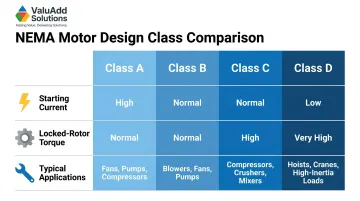
NEMA motor design class significantly impacts inrush characteristics:
| NEMA Design | Starting Current | Locked-Rotor Torque | Typical Applications |
|---|---|---|---|
| Design A | High | Normal | Fans, blowers, pumps requiring higher breakdown torque |
| Design B | Normal | Normal | Standard industrial applications (most common) |
| Design C | Normal | High | Conveyors, crushers, reciprocating pumps |
| Design D | Low | Very High | High peak loads with flywheels (punch presses, hoists) |
Motor horsepower, supply voltage, and load inertia also shape inrush severity. NEMA MG1 standards provide detailed motor starting current classifications for precise system design.
Historical Context: Wye-Delta Starting
These design differences across NEMA classes reflect a long-standing engineering challenge. High-power motors historically used a wye (star) winding configuration at startup to reduce voltage per winding and lower locked-rotor current, then switched to delta for running. Soft starters and variable frequency drives have since replaced this approach, offering finer control with less mechanical switching complexity.
How Much Current Does a Motor Draw on Startup?
Standard Magnitude Range
Motors typically draw 6–10 times their full-load ampere (FLA) rating during locked-rotor conditions at startup. To precisely determine a motor's LRC, NEMA MG1 and NEC 430.7(B) use Locked-Rotor Indicating Code Letters:
| NEMA Code Letter | kVA per HP with Locked Rotor |
|---|---|
| F | 5.00 – 5.59 |
| G | 5.60 – 6.29 |
| H | 6.30 – 7.09 |
| J | 7.10 – 7.99 |
Example: A 30 HP, 460V Code G motor draws a maximum starting current of approximately 237 amps (6.29 kVA/HP × 30 HP = 189 kVA ÷ 0.796 kV = 237A).
Duration Matters as Much as Magnitude
Protection devices respond to thermal energy—expressed as I²t (current squared multiplied by time)—not just peak current alone. A very brief 10× FLA spike may not trip a properly selected breaker, but an extended period at 6–8× FLA while a large, high-inertia load accelerates can approach trip thresholds. That's why NEC 430.52 permits time-delay fuses and inverse-time breakers sized well above FLA — they must ride through startup without sacrificing overload protection during run.
Variables Affecting Real-World Inrush Profiles
Actual inrush profiles vary based on:
- Motor horsepower and voltage class
- Supply system impedance (can amplify or dampen the peak)
- Load type: Centrifugal pumps exhibit different inrush than positive displacement compressors or conveyors with backstops
- Motor temperature: Whether starting cold or recently stopped (residual flux affects first-cycle peak)
A centrifugal pump starting against a closed discharge valve accelerates quickly, producing a sharper but shorter inrush spike. A conveyor with a loaded belt and a backstop, by contrast, sustains elevated current longer as it overcomes breakaway torque — a profile that demands closer attention to I²t limits when sizing protection.
What Happens When Motor Inrush Current Goes Unmanaged
Nuisance Tripping and Production Downtime
Breakers or fuses not properly selected for motor starting duty can trip during every startup—even without any actual fault. This causes production stoppages that are disruptive and difficult to diagnose if the root cause isn't understood. The problem is especially common in facilities where motors cycle on and off frequently, such as batch processing plants or automated production lines.
Winding and Insulation Degradation Over Repeated Starts
Each inrush event subjects motor windings to thermal stress as current heats conductors and insulation. While a single inrush event rarely causes immediate damage, cumulative thermal cycling from repeated starts progressively degrades insulation integrity and shortens motor service life.
IEC 60034-12 requires motors to withstand two successive cold starts and one hot start. Exceeding the starts-per-hour limit—defined by NEMA MG1 clause 12.54 based on horsepower, poles, and load inertia—requires consulting the motor manufacturer to prevent premature insulation failure.
Mechanical Torque Shock on Driven Equipment
The torque surge accompanying direct-on-line starting creates sudden mechanical shock propagating through couplings, gearboxes, shafts, and into driven equipment. Real-world consequences include:
- Pipe damage and seal failure from water hammer in pump systems
- Snapped belts and damaged gear reducers on conveyors
- Stressed valve assemblies and piston rods in compressors
Research shows that DOL starting generates transient torque pulsations exceeding full-load torque, causing shock-loading that damages mechanical components—a failure mode that accumulates across thousands of start cycles in high-cycle applications.
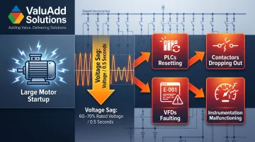
Voltage Sag and System-Wide Power Quality Impact
When a large motor starts, high inrush current flowing through supply system impedance causes a momentary voltage dip affecting all equipment on the same bus. According to IEEE Std 1250, voltage sag to 60–70% of rated voltage for just 0.5 seconds can de-energize contactors, relays, and magnetic coils.
Sensitive devices—PLCs, VFDs already in operation, control systems, and instrumentation—may reset or malfunction during these sags. In water treatment plants and industrial facilities where multiple motors share a common bus, unmanaged inrush current can cascade into system-wide disruptions that are far costlier than the motor start itself.
How to Reduce Motor Inrush Current: Comparing Starting Methods
Direct-On-Line (DOL) Starting: The Uncontrolled Baseline
DOL applies full supply voltage to motor terminals instantly at startup, producing maximum inrush current (600–800% FLA) and maximum torque shock. It's the simplest, lowest-cost method and acceptable for small motors (typically under 5 HP) or applications with infrequent starts, but represents the worst case for both electrical system stress and mechanical shock.
Star-Delta (Wye-Delta) Starting
Connecting motor windings in star configuration at startup reduces voltage across each winding by 1/√3, cutting inrush current to approximately 33% of DOL value (~200% FLA).
Limitations:
- Unavoidable torque dip occurs during transition from star to delta
- Motor must be specifically wound to allow configuration switch
- Not suitable for loads that cannot tolerate brief torque interruption
Engineering analysis shows that while star-delta reduces starting current effectively, the transition spike can approach DOL levels momentarily, potentially causing the very problems you're trying to avoid.
Soft Starters for Controlled Voltage Ramp-Up
Electronic soft starters use SCRs (silicon controlled rectifiers) to gradually ramp voltage from a low initial value to full voltage over a programmable period. This reduces both inrush current (to 150–400% FLA) and startup torque — protecting electrical systems and driven equipment without the transition spike that plagues star-delta methods.
ValuAdd's medium voltage soft starters are built for industrial applications like pumps, compressors, and conveyors where stepless acceleration matters. Key control features include:
- Programmable initial voltage levels
- Adjustable ramp time ranges
- Current limit settings for precise control
- Class E2 load break compliance for maximum safety
Because motor torque is proportional to voltage squared, reducing voltage to 40% generates only 16% of locked-rotor torque, which allows for extremely gentle starts on sensitive mechanical systems like pump impellers or loaded conveyors.
Variable Frequency Drives (VFDs) for Full Speed and Frequency Control
VFDs independently control both voltage and output frequency during startup, ramping from near-zero frequency up to target speed at a controlled rate. This nearly eliminates inrush current entirely (100–150% FLA)—the motor sees gradually increasing frequency rather than full-voltage instantaneous energization.
VFDs also enable precise speed control during normal operation, making them the preferred solution when both inrush reduction and process speed control are required.
For medium voltage applications where harmonic distortion is also a concern, ValuAdd's H-Bridge multi-level VFD technology uses overlapping wave output to closely approximate a true sine wave, achieving:
- Total Harmonic Distortion Voltage (THDv) < 8%
- Total Demand Distortion Current (TDDi) < 5%
- Full IEEE 519 compliance without external filtering
These drives support voltages up to 7.2 kV and motor ratings from 300 HP to 12,000 HP, making them ideal for large-scale industrial applications.
Quick Comparison Table
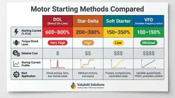
| Starting Method | Starting Current | Torque Shock | Relative Cost | Best Application |
|---|---|---|---|---|
| DOL | 600–800% FLA | Maximum | Lowest | Small motors, infrequent starts |
| Star-Delta | ~200% FLA | Moderate (with transition spike) | Low | Fixed loads, <200 HP |
| Soft Starter | 150–400% FLA (adjustable) | Minimal | Moderate | Most industrial applications |
| VFD | 100–150% FLA | Minimal | Highest | Speed control required, critical processes |
Sizing Breakers and Overloads for Motor Starting
Why Standard Breakers Nuisance-Trip on Motor Starts
Standard thermal-magnetic breakers have trip curves designed for continuous overloads and faults—not the predictable, temporary overcurrent of motor starting. NEC Article 430 allows fuses or breakers sized at multiples of FLC specifically to ride through starting current.
The NEC intentionally sizes motor branch-circuit short-circuit protection much higher than conductor ampacity to allow the 5–7× starting current surge to pass without nuisance tripping:
| Protective Device Type | Maximum % of Motor FLC (NEC Table 430.52) |
|---|---|
| Inverse-Time Breaker | 250% |
| Dual-Element Time-Delay Fuse | 175% |
| Instantaneous-Trip Breaker (MCP) | 800% (adjustable to 1100%) |
Matching the trip curve to the actual inrush profile of your motor is essential for reliable operation.
Overload Relay Coordination for Sustained Protection
Overload relays (thermal or electronic) protect motors from sustained running overloads—separate from branch circuit protection handling fault current. Per NEC 430.32(A)(1), overload relays are sized using motor nameplate FLA:
- Motors with service factor ≥1.15 or temperature rise ≤40°C: Size at 125% of nameplate FLA
- All other motors: Size at 115% of nameplate FLA
Overload relay trip classes correspond to different permissible starting times:
- Class 10: Trips in ≤10 seconds at 600% (hermetic motors, submersible pumps)
- Class 20: Trips in ≤20 seconds at 600% (standard industrial applications)
- Class 30: Trips in ≤30 seconds at 600% (high-inertia loads)
Select the trip class based on your motor's expected acceleration time to avoid nuisance trips during normal starting.
Impact of Starting Method on Protection Sizing and Cost
When a soft starter or VFD limits inrush, the peak current your protection system must handle drops considerably. That reduction cascades through the entire installation, allowing smaller-rated components across the board:
- Smaller breakers and fuses rated for lower interrupt capacity
- Reduced conductor sizing and conduit fill
- Lower-rated switchgear and panel equipment
- Decreased installation labor on wire pulling and terminations
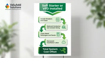
The investment in a soft starter or VFD extends well beyond motor protection. Reduced infrastructure requirements across the electrical distribution system often offset a significant portion of the device cost itself.
Frequently Asked Questions
What is inrush current in simple terms?
Inrush current is the brief, high surge of electrical current a device draws the instant it's switched on—much higher than its normal running current—before internal components stabilize. It's normal and predictable behavior, not a fault.
What causes the high inrush current?
Inrush stems from a few distinct mechanisms: capacitors behave as near-short-circuits at startup, transformers saturate magnetically at energization, and motors draw locked-rotor current before back-EMF develops. Motors typically generate the highest-magnitude inrush in industrial settings.
Why do motors have high inrush current?
A stationary motor generates no back-EMF, meaning applied voltage is opposed only by low stator winding resistance at startup. This results in very high current flow until the rotor accelerates and back-EMF builds to limit current to normal running levels.
How much current does a motor draw on startup?
Most AC induction motors draw 6–10 times their full-load ampere (FLA) rating during startup (locked-rotor current). The exact value varies by NEMA motor design class (A, B, C, or D), horsepower, and load characteristics. Nameplate code letters specify the exact starting kVA per horsepower for that motor.
How can you reduce the inrush current of a motor?
Common options include soft starters (gradual voltage ramp-up), VFDs (near-zero inrush with full speed control), and star-delta starters (inrush reduced to roughly one-third of DOL at lower cost). The right choice depends on motor size, starting frequency, and whether speed control is needed.
Can your breaker trip because of inrush current?
Yes—if breakers aren't sized for motor starting duty, inrush can exceed the instantaneous trip threshold and cause nuisance tripping with no actual fault present. NEC Article 430 covers motor branch circuit protection sizing, and motor circuit protectors (MCPs) with adjustable trip points are built specifically to handle this.