
Introduction
Engineers and technicians designing industrial power distribution systems face a recurring challenge: determining which busbar cross-section matches a given AWG wire gauge for equivalent current-carrying capacity. Unlike wire, busbars are sized by physical dimensions — thickness × width in inches or millimeters — not a gauge number.
This dimensional difference creates confusion when designing switchgear, motor control centers, or VFD panel assemblies where wire and busbar coexist. A 4/0 AWG cable and a 1/4" × 3" copper busbar may both handle similar current, but selecting the wrong dimension can lead to overheating, voltage drop, or system failure.
Use this guide to match wire gauges to the right busbar dimensions, understand temperature derating and orientation effects, and apply connection practices that hold up in real industrial installations.
Key Takeaways
- AWG maps to busbar size through cross-sectional area (circular mils or mm²) and ampacity — not a direct 1:1 swap
- Aluminum busbars need roughly 1.6× the cross-section of copper to carry equivalent current
- Standard ampacity ratings assume 40°C ambient with 30°C rise; enclosed panels and high temps require derating
- Vertical busbar mounting enhances convection cooling versus horizontal flat orientation, increasing effective ampacity
- Verify sizing against manufacturer ampacity charts and NEC derating factors before finalizing any design
Understanding Wire Gauge and Busbar Sizing Basics
AWG (American Wire Gauge) is a logarithmic sizing system where lower gauge numbers indicate larger wire diameters and higher current capacity. Each 3-gauge step approximately doubles the cross-sectional area — for example, 10 AWG has roughly twice the area of 13 AWG, and 4 AWG has twice the area of 7 AWG.
Where AWG assigns wire a single number, busbars abandon the gauge system entirely and use physical dimensions (width × thickness) measured in inches or millimeters. A busbar might be specified as "1/4 × 2 inches" or "6 × 50 mm," with no gauge designation.
Cross-sectional area is the common language between wire and busbar sizing. Both are ultimately selected based on how many amps they need to carry safely without exceeding temperature limits. Circular mils (cmil) serve as the bridge unit — one circular mil equals the area of a circle with a 1-mil (0.001-inch) diameter. NEC wire tables and CDA busbar tables both reference circular mils, enabling direct comparisons when converting wire gauge to busbar dimensions.
Wire Gauge to Busbar Size Conversion Chart
The table below maps common AWG wire gauges to their cross-sectional areas and corresponding copper busbar dimensions that provide comparable or greater ampacity under standard conditions.
Standard Conditions: 75°C copper conductor insulation rating, 30°C ambient temperature, not more than three current-carrying conductors in raceway (for wire); 40°C ambient with 30°C temperature rise, horizontal mounting on edge in still air (for busbars). Source: NEC Table 310.15(B)(16) and CDA Copper Busbar Tables.
| AWG / kcmil Size | Area (cmil) | Area (in²) | Wire Ampacity (A) | Equivalent Copper Busbar Dimensions | Busbar Ampacity (A) |
|---|---|---|---|---|---|
| 14 AWG | 4,110 | 0.0032 | 20 | 1/16" × 1/2" | ~80 |
| 12 AWG | 6,530 | 0.0051 | 25 | 1/16" × 3/4" | ~120 |
| 10 AWG | 10,380 | 0.0081 | 35 | 1/16" × 1" | ~160 |
| 8 AWG | 16,510 | 0.0129 | 50 | 1/8" × 1/2" | ~170 |
| 6 AWG | 26,240 | 0.0206 | 65 | 1/8" × 3/4" | ~210 |
| 4 AWG | 41,740 | 0.0327 | 85 | 1/8" × 1" | 270 |
| 2 AWG | 66,360 | 0.0521 | 115 | 1/8" × 1 1/4" | ~320 |
| 1/0 AWG | 105,600 | 0.0829 | 150 | 1/8" × 1 1/2" | 385 |
| 2/0 AWG | 133,100 | 0.1045 | 175 | 3/16" × 1" | 340 |
| 3/0 AWG | 167,800 | 0.1317 | 200 | 3/16" × 1 1/4" | ~400 |
| 4/0 AWG | 211,600 | 0.1662 | 230 | 3/16" × 1 1/2" or 1/4" × 1" | 480 / 400 |
| 250 kcmil | 250,000 | 0.1963 | 255 | 1/4" × 1" or 1/8" × 2" | 400 / 495 |
| 350 kcmil | 350,000 | 0.2748 | 310 | 1/4" × 1 1/2" | ~550 |
| 500 kcmil | 500,000 | 0.3926 | 380 | 1/4" × 2" | 710 |
Important Notes:
- A 1/8" × 1" copper busbar (0.125 in²) carries 270 A — nearly 55% more than a similarly sized 2/0 AWG cable (0.1045 in²) at 175 A — because busbars dissipate heat more efficiently than insulated conductors.
- These values are starting points, not direct substitutions. Final selection must account for installation environment, orientation, and derating factors specific to your application.
- Vertical mounting and active airflow both increase busbar ampacity above the values shown, which assume horizontal mounting in still air.
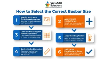
How to Use This Chart:
- Identify the maximum continuous amperage of your circuit
- Add 25% safety margin per NEC continuous load requirements (load operating ≥3 hours)
- Look up the required wire gauge or busbar equivalent in the ampacity column
- Confirm busbar dimensions from the conversion column
- Apply derating factors for your specific installation conditions
- Verify final selection with manufacturer specifications and thermal testing for critical applications
How to Select the Right Busbar Size for Your Application
Maximum Continuous Current Drives Sizing
Always size based on maximum continuous current — the highest amperage the busbar will carry for three or more consecutive hours. Design current should include safety margins and NEC derating factors (typically 125% of the continuous load).
Common mistakes:
- Using peak inrush current instead of continuous current (leads to severe oversizing)
- Ignoring the NEC 80% rule for continuous loads
- Failing to account for future load growth
In VFD panel assemblies and motor control centers — where a single busbar distributes power to multiple loads simultaneously — accurate continuous current calculation is the difference between a protected system and an undersized one.
Ambient Temperature Affects Ampacity
Standard ampacity ratings assume a 40°C ambient environment. Installations in enclosed NEMA enclosures, near heat-generating equipment, or in industrial facilities with elevated ambient temperatures require derating.
General Derating Guidelines:
- 50°C ambient: Derate by ~10%
- 60°C ambient: Derate by ~20%
- 70°C ambient: Derate by ~30%
For example, a busbar rated for 400 A at 40°C ambient should be derated to approximately 320 A in a 60°C environment. Consult manufacturer derating tables for precise values.
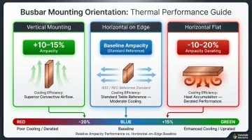
Busbar Orientation and Spacing
Vertical mounting vs. horizontal mounting significantly impacts heat dissipation:
- Vertical mounting uses chimney-effect convection to improve cooling — effective ampacity increases 10-15% vs. horizontal flat
- Horizontal on edge is the standard orientation assumed in most published ampacity tables
- Horizontal flat offers the poorest cooling; derate by 10-20% in this configuration
Multi-bar spacing: In assemblies with multiple parallel busbars, maintain adequate spacing (typically 0.5-1 inch minimum) to prevent heat buildup between bars and allow airflow.
AC vs. DC Busbar Sizing
DC sizing focuses on three factors:
- Resistance per foot (directly determines voltage drop over run length)
- Voltage drop across the full circuit length
- Continuous current capacity at operating temperature
AC sizing must account for additional variables:
- Skin effect — AC concentrates near the conductor surface at 50/60 Hz, raising effective resistance; CDA ampacity tables list skin effect ratios exceeding 1.0 for larger bars
- Multi-bar assemblies reduce skin effect by expanding total surface area
- Laminated busbar configurations (multiple thin bars stacked) outperform single thick bars in high-frequency AC applications
In motor control systems and VFD installations, proper AC busbar sizing is especially important — harmonic currents from drive outputs amplify skin effect losses, so undersized bars compound efficiency problems that voltage drop alone won't reveal.
Copper vs. Aluminum Busbars: Sizing Differences
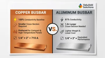
Conductivity and Cross-Section Requirements
Aluminum has approximately 61% the conductivity of copper, meaning an aluminum busbar must have a larger cross-section to carry the same current. The standard conversion multiplier is approximately 1.6× the cross-sectional area — if a copper busbar requires 0.250 in², the aluminum equivalent needs roughly 0.400 in².
Practical Implications:
- Aluminum: Lighter weight, lower material cost per pound, common in large-current utility distribution
- Copper: Preferred for compact panels, high-temperature environments, and applications where corrosion resistance is critical
Example: A 1/4" × 2" copper busbar (0.500 in²) rated for 710 A would require an aluminum busbar of approximately 1/4" × 3" (0.750 in²) to achieve comparable performance.
Connection and Corrosion Considerations
Connecting aluminum busbars to copper conductors creates galvanic corrosion risk. NEC 110.14 requires:
- Use connectors explicitly listed for AL/CU intermixed service
- Install bimetallic transition plates at flat busbar connections
- Apply oxide-inhibiting compound (Penetrox or Noalox) immediately after wire-brushing the aluminum surface
High contact resistance at aluminum-copper interfaces can cause localized overheating — a precursor to insulation failure and unplanned downtime. Follow manufacturer torque specifications at every connection and schedule periodic re-torque inspections, since aluminum creeps under sustained load.
Wire-to-Busbar Connection Tips for Industrial Systems
Proper Torque and Contact Surface Treatment
Torque specifications are non-negotiable. Under-torquing creates high contact resistance; over-torquing damages hardware or busbars. Always follow manufacturer values — for example, BURNDY K11A30U universal terminals require 275 in-lb.
Surface treatment reduces contact resistance:
- Tin plating: Widely used to inhibit oxide formation on copper surfaces
- Silver plating: Superior for high-current applications, lowers contact resistance further
Ensure the compression lug's wire gauge rating matches the wire being terminated. Mismatched lugs create bottlenecks and potential hot spots.
Voltage Drop at Connection Points
Even a correctly sized wire and busbar can suffer excessive voltage drop if the connection point has high contact resistance. NEC recommends limiting voltage drop to 3% for branch circuits and 5% total for combined feeder and branch circuits.
Common causes of high contact resistance:
- Corrosion or oxidation
- Improper torque
- Mismatched or undersized hardware
- Stacked lugs on a single bolt point
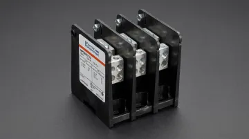
Multi-Conductor Distribution
Stacked lugs — one of the causes of high contact resistance listed above — are especially common in industrial control panels. Avoid placing multiple lugs on a single busbar bolt point. Instead, use:
- UL-listed power distribution blocks (such as BURNDY U-BLOK)
- Terminal blocks rated for aggregate current
- Multi-wire circuit breaker terminals compliant with UL 508A tap rules
Frequently Asked Questions
How to select busbar size?
Busbar size is selected based on required ampacity (maximum continuous current), ambient temperature, conductor material (copper or aluminum), and installation orientation. Use manufacturer ampacity charts to match busbar dimensions to current requirements, then apply derating factors for your specific environment.
What gauge wire from battery to busbar?
Wire gauge depends on current draw and wire length. In an industrial control panel drawing 50 A, 6 AWG copper is typical for short runs. High-current applications (100 A+) require 1/0 AWG or larger, and the wire gauge must always match or exceed the busbar's rated ampacity.
Can 4 AWG carry 100 amps?
No. 4 AWG copper is rated for 85 A at 75°C under standard NEC conditions. For a sustained 100 A continuous load, NEC requires 125 A capacity (100 A × 1.25), making 1 AWG (130 A rating) the minimum appropriate size.
Can I use cable instead of busbar?
Cable can replace busbar for point-to-point connections, but busbars are preferred for high-current, multi-tap applications. Busbars offer lower resistance, better heat dissipation, and simpler tap-off connections — reducing installation complexity in switchgear and motor control centers.
What is the equivalent busbar size for 4/0 AWG wire?
4/0 AWG copper wire has a cross-sectional area of approximately 211,600 circular mils (about 0.166 in²). A copper busbar of 1/4" × 1" (0.250 in², 400 A) or 3/16" × 1 1/2" (0.281 in², 480 A) provides comparable or greater cross-section with similar ampacity under standard conditions.
Does temperature affect busbar ampacity ratings?
Yes — standard ampacity ratings assume 40°C ambient with a 30°C rise. Higher ambient temperatures, such as inside enclosed NEMA enclosures or near heat sources, reduce effective ampacity and require derating per NEC 310.15 to prevent conductor overheating and insulation breakdown.