Introduction
Transfer switches are the critical link between utility power and backup generators in emergency power supply systems (EPSS). When utility power fails, these switches must transition to backup power within seconds. Any delay or failure can jeopardize operations in industrial facilities, shut down critical hospital equipment, or halt emergency services.
According to NFPA 110, an ATS is a potential single-point failure because both normal and emergency power flow through the same equipment to critical loads.
Despite this, many facilities skip comprehensive transfer switch testing. Some lack bypass isolation features and avoid de-energizing critical loads for maintenance; others don't understand the three-layer testing protocol required for reliable performance.
The cost of neglect is real. Contact wear, relay failure, and mechanical binding are all failure modes that weekly visual inspections and monthly operational testing are designed to catch before an actual emergency.
Understanding those failure risks is exactly why a structured testing approach matters. This guide covers the tools required, three core testing methods (visual/mechanical, electrical, and functional), how to interpret results, and common pitfalls when testing both manual and automatic transfer switches.
Key Takeaways
- Transfer switch testing covers three areas: visual/mechanical inspection, electrical tests, and functional/operational testing
- De-energize all power sources before internal inspection — and never use compressed air on internal components
- Automatic transfer switches (ATS) must be tested monthly per NFPA 110, with weekly visual inspections of the full EPSS
- Key pass criteria: insulation resistance ≥ 2 MΩ, contact resistance within 50% of lowest value, transfer time within 10 seconds
- Document all test results; deviations from manufacturer specs need immediate investigation and corrective action
What You Need to Test a Transfer Switch
Transfer switches operate at high voltages with two live sources, so preparation matters. Using the wrong tools or skipping preconditions can produce false readings that mask real faults—or damage sensitive components outright.
Tools and Equipment Required
Measurement Instruments:
- Low-resistance ohmmeter or microhmmeter (4-wire Kelvin method) for contact/pole resistance testing
- Insulation resistance tester (megohmmeter) capable of 500 V dc and 1000 V dc output per ANSI/NETA standards
- Calibrated torque wrench for verifying bolted connection integrity
- Multimeter or voltage/frequency meter for source verification
Operational Tools:
- Manual operating handle (usually supplied with the switch)
- Timer or stopwatch to verify transfer timing against NFPA 110 requirements
- Infrared camera (optional) for thermographic inspection of bolted connections as an alternative or supplement to low-resistance testing
Cleaning Supplies:
- Flashlight or work light
- Clean dry cloth or soft brush
- Vacuum cleaner (never use compressed air)
Preconditions and Setup
Lockout/Tagout is mandatory before any internal inspection or manual operation testing. OSHA 1910.147 requires all four steps completed in sequence:
- Isolate all energy sources (both normal and alternate feeds)
- Apply locks and tags to each isolation point
- Release any stored energy in the switch mechanism
- Physically verify de-energization before proceeding
Pre-Test Setup:
- Confirm the unit is accessible, well-lit, and clear of obstructions
- Conduct as-found tests before cleaning the unit to preserve baseline condition data for comparison
- Verify you have the manufacturer's specifications and previous test records for trending
- Ensure all personnel are trained and wearing appropriate PPE per NFPA 70E requirements
How to Test a Transfer Switch: Three Core Procedures
Transfer switch testing covers three distinct procedures, each verifying a different layer of reliability: physical condition, electrical integrity, and operational behavior. All three must be completed for a thorough assessment. Skipping any layer risks missing deterioration that only surfaces during an actual emergency.
Method 1: Visual and Mechanical Inspection
Visual and mechanical inspection assesses the physical condition of the switch—anchorage, alignment, grounding, cleanliness, lubrication, contact condition, and bolted connections—to catch visible deterioration before electrical or functional testing begins.
Tools/Equipment Needed:
- Flashlight or work light
- Clean dry cloth or soft brush
- Vacuum cleaner
- Calibrated torque wrench
- Low-resistance ohmmeter (for bolted connections)
Step-by-Step Procedure:
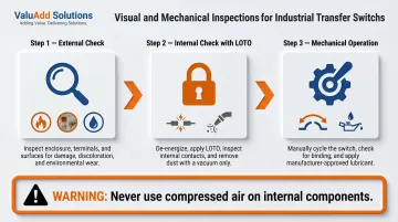
External check: Inspect the unit for signs of heat damage, vibration, corrosion, moisture intrusion, or contamination. Verify all covers, barriers, and arc chutes are properly fastened and that manual transfer warnings are visible. Check for discolored metal, melted insulation, or burning odors—all indicators of overheating.
Internal check (power OFF, LOTO applied): Remove barriers and arc chutes, then inspect contacts for pitting, burning, or excessive wear. Clean the unit using a vacuum or dry cloth only—never compressed air or emery cloth. Eaton warns: "Do not blow debris into the switching device," and MGI EPSS guidance states that compressed air "may have a detrimental effect by forcing dirt and debris into the switch mechanism."
Mechanical operation: Insert the manual operator handle and operate the switch between Normal and Emergency positions. Confirm smooth movement without binding and verify positive mechanical interlocking between sources. Return the switch to Normal position and store the handle. Verify appropriate lubrication on all moving current-carrying parts per manufacturer specifications—ASCO 7000 Series manuals state: "Do not use oil; order lubrication kit 75-100."
Perform contact/pole resistance measurement during this phase. Per ANSI/NETA standards, values deviating from adjacent poles or similar switches by more than 50% of the lowest reading require investigation—a codified threshold for impending contact failure.
Method 2: Electrical Testing
Electrical testing verifies insulation integrity across all control wiring and measures resistance at main contacts and bolted connections. Unlike visual inspection, this method quantifies degradation with specific numerical values compared against published thresholds.
Tools/Equipment Needed:
- Insulation resistance tester (megohmmeter) at 500 V dc or 1000 V dc
- Microhmmeter or dc millivolt drop tester for contact/pole resistance
- Calibrated torque wrench for bolted connection verification
Step-by-Step Procedure:
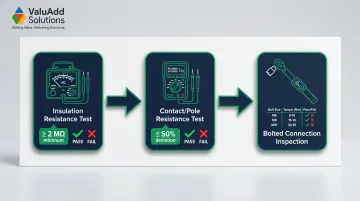
Insulation resistance test: Disconnect any solid-state components or plugs that cannot tolerate high voltage. Apply 500 V dc for 300-volt rated control wiring or 1000 V dc for 600-volt rated wiring for one minute. Record readings. The minimum acceptable insulation resistance is 2 MΩ per ANSI/NETA standards—anything below this threshold indicates moisture contamination, insulation breakdown, or compromised control wiring.
Contact/pole resistance test: Using the manual transfer operation, position the switch in the Normal source position and measure contact resistance. Repeat for the Alternate source position. Record all pole-to-pole values. Investigate any microhm or dc millivolt drop values deviating from adjacent poles by more than 50% of the lowest value.
Bolted connection inspection: Check all bolted electrical connections using a low-resistance ohmmeter or calibrated torque wrench. Bolt torque levels must comply with manufacturer's published data or, where unavailable, ANSI/NETA Table 100.12. Loose bolted connections cause resistance buildup, overheating, and eventual failure.
During this phase, calibrate and set all control relays and timers per ANSI/NETA Section 7.9. Verify settings match manufacturer's design requirements before proceeding to functional testing—relay and timer drift is common over time and can delay transfer or block re-transfer entirely.
Method 3: Functional and Operational Testing (ATS)
Functional testing simulates real-world power loss scenarios to verify that the ATS transfers load automatically, within required timing parameters, and correctly re-transfers upon power restoration—including engine start/stop sequencing. Failures here typically trace back to relay drift, incorrect timer settings, or contact degradation missed in earlier phases.
Tools/Equipment Needed:
- Multimeter or voltage/frequency meter to verify source levels
- Access to generator start controls
- ATS controller with indicator LEDs
- Timer or stopwatch to verify transfer timing
Step-by-Step Procedure:
Source verification: Close the normal source circuit breaker and confirm the Utility Available LED illuminates. Verify phase-to-phase voltages at utility terminals. Then close the alternate source breaker, start the generator, and confirm the S2 (Alternate) Available LED illuminates at correct voltage and frequency. Shut down the generator and place it in automatic start mode.
Simulate utility failure: Open the Source 1 (normal side) breaker to simulate an outage. Observe that the delay-to-engine-start timer runs its full cycle before the generator starts. Confirm the ATS transfers to the generator source when S2 reaches preset voltage and frequency levels, with the S2 position LED illuminating. Transfer should occur within 10 seconds per NFPA 110 requirements—this is a strict mandate for healthcare facilities, where life safety and critical branches must restore power within 10 seconds.
Re-transfer and cool-down: Reclose the Source 1 breaker. Confirm the delay-to-utility timer completes before the ATS transfers back. Verify the delay-engine-stop timer then runs a minimum 5-minute unloaded cool-down cycle (required by NFPA 110 except for air-cooled prime movers ≤15 kW) before the generator shuts down.
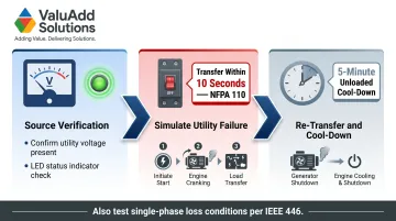
Also simulate loss of emergency power and all single-phase conditions during this test. IEEE 446 warns that three-phase motors can continue running when one phase fails, inducing a voltage on the failed phase that may prevent the ATS sensing circuit from detecting the loss—a failure mode that goes undetected without deliberate testing.
How to Interpret Transfer Switch Test Results
Test readings only protect operations if they are correctly interpreted. Misreading a marginal result as acceptable can mean discovering a failed switch during an actual emergency rather than during scheduled maintenance. Compare every reading against both manufacturer specifications and previous baseline data.
Normal/Acceptable Results
- Insulation resistance reads ≥ 2 MΩ on all control wiring
- Contact/pole resistance values are consistent across all poles and within 50% of the lowest measured value
- The ATS transfers load within 10 seconds
- All timing sequences match manufacturer specifications
- No signs of overheating, pitting, or mechanical binding
Document results, apply a field-tested label per NFPA standards, and schedule the next routine test. Store results for trending analysis — gradual degradation over months reveals impending failures before they become critical.
Minor Issues / Watch List
- Insulation resistance approaches but remains above 2 MΩ
- Bolt torque is at the lower end of tolerance
- One timer setting is slightly off but within acceptable range
- Contacts show minor surface deposits but no pitting
Clean contacts (dry cloth only), re-torque bolted connections, re-calibrate timers, and increase monitoring frequency. These are early warning signs — address them before they cross into failure territory.
Out-of-Spec / Action Required
- Insulation resistance below 2 MΩ
- Contact resistance deviating >50% from the lowest pole value
- Transfer time exceeding 10 seconds
- Switch fails to transfer or re-transfer during functional test
- Signs of overheating (discolored metal, burning odor, melted insulation)
Remove from service for repair, contact a qualified technician, and replace any worn contacts or failed components with manufacturer-specified parts. For harsh industrial environments, specify UL Listed, NEMA 4X-rated replacement switches to maintain original performance and enclosure ratings. ValuAdd's SIRCOVER UL manual transfer switches meet both certifications and are sized for demanding industrial applications.
Safety, Common Errors & Best Practices
Most transfer switch test failures trace back to procedural missteps, not equipment problems. Knowing what to avoid is as important as following the correct sequence.
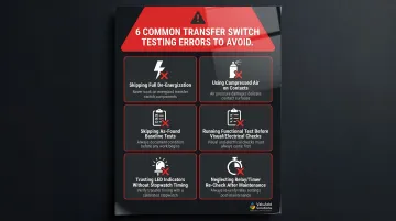
Common Testing Errors:
- Failing to fully de-energize both power sources before internal work
- Using compressed air or emery cloth on contacts, which lodges debris or damages contact surfaces
- Skipping as-found tests before cleaning, which eliminates your baseline comparison data
- Running the functional test before completing visual and electrical checks, which risks misleading results
- Trusting LED indicators as proof of correct transfer—LEDs can illuminate even when timing sequences are out of spec; always time transfers with a stopwatch
- Neglecting to re-check relay and timer settings after any maintenance or component replacement, since settings can drift or shift during repair work
These errors are easy to avoid with a disciplined checklist approach. The safety precautions below form the foundation of that discipline.
Key Safety Precautions:
- Always apply full lockout/tagout (LOTO) to both the normal and alternate power sources before internal inspection or manual switch operation
- Wear appropriate PPE for electrical work (arc-flash rated clothing, insulated gloves, safety glasses) in accordance with NFPA 70E
- Only qualified workers should perform internal inspection and electrical testing; external visual inspection may be performed by trained operators
- Keep the work area clean and well-lit; never use a blower—use a vacuum, dry cloth, or soft brush only
Conclusion
Reliable transfer switch performance depends on a structured, three-part testing program carried out at the intervals required by NFPA 110. Each layer targets different failure modes:
- Visual/mechanical inspection catches physical deterioration, loose connections, and environmental damage
- Electrical testing quantifies insulation breakdown and contact resistance degradation
- Functional testing proves real-world operational readiness under actual load conditions
Out-of-spec readings are early failure warnings, not minor variances. A transfer switch that reads marginal today is a transfer switch that fails during the next power outage. Address any abnormal results promptly with qualified technicians.
When replacement parts are needed, prioritize UL Listed, NEMA-compliant components rated for the specific application and environment. ValuAdd's technical specialists can help identify the right replacement components for transfer switch maintenance programs in industrial facilities.
Frequently Asked Questions
How often should automatic transfer switches be tested?
Per NFPA 110, ATS units require monthly operational testing and a full weekly inspection of the EPSS — covering batteries, battery chargers, and the switch. The 10-second transfer criterion must be confirmed annually if it isn't consistently met during monthly tests.
What are the symptoms of a bad transfer switch?
Common warning signs include failure to transfer during a power outage, delayed or erratic switching, burning smells, discolored or pitted contacts, tripped breakers, LED indicators failing to change state, or the generator starting but the load not transferring.
What causes ATS failure?
Typical failure causes include contact wear or arcing damage, control board or relay failure, loose bolted connections causing resistance buildup, corrosion from moisture or dust contamination, and mechanical binding due to insufficient lubrication or physical damage.
What does an ATS maintenance checklist include?
A standard ATS maintenance checklist covers:
- Visual inspection of physical condition and cleanliness
- Lubrication check and manual transfer operation test
- Insulation resistance test on control wiring
- Contact and pole resistance measurement
- Relay and timer calibration
- Full functional test simulating power loss and restoration
Can I test a transfer switch myself, or do I need a qualified electrician?
External visual checks — dust buildup, heat signs, indicator LEDs — may be performed by trained operators. Any internal inspection, electrical testing, or functional testing involving live circuits or control wiring must be performed by qualified electrical workers under NFPA 70E requirements.
What is the 10-second transfer rule for transfer switches?
NFPA 110 and NFPA 99 require essential electrical systems to restore power within 10 seconds of a normal power loss. If monthly tests don't consistently hit this mark, annual verification is required to confirm the system still meets the criterion.