Introduction
Errors in electrical panel design don't surface quietly. A misplaced disconnect costs hours of rework; an undersized enclosure may require a complete rebuild. According to industry data, approximately 67% of electrical panel failures in manufacturing facilities stem from design-phase oversights rather than component defects.
This work falls to qualified electrical engineers, system integrators, and plant engineers who need to get it right the first time. Poorly designed panels create cascading problems:
- Overheating shortens component lifespan
- Nuisance trips halt production
- Safety failures trigger OSHA citations
- Failed inspections delay project completion
FM Global loss data (2014-2024) documented $199.57 million in losses from a single furnace explosion — traced to a control system malfunction caused by inadequate surge protection.
Understanding these risks makes good design non-negotiable. This guide covers the essential panel components, layout and wiring best practices, relevant standards, and how to avoid the most common design-phase mistakes.
Key Takeaways
- Successful panel design integrates component selection, physical layout, wiring, thermal management, and standards compliance as a single coordinated system
- Size enclosures around functional load requirements first, then add 20% capacity for future expansion
- Separate AC/DC circuits physically, keep high-voltage runs away from signal wiring, and isolate heat-generating components from sensitive electronics
- UL 508A, NFPA 79, and NEC Article 409 compliance is mandatory for North American industrial environments
- Most field failures trace back to poor documentation, skipped validation, or undersized enclosures — all preventable during the design phase
Key Components of an Industrial Electrical Panel
A well-designed panel groups components by function and power level. Every component plays a defined role, and the design must account for interactions between them—heat dissipation, electromagnetic interference (EMI), voltage levels, and maintenance accessibility all influence placement decisions.
Power Distribution Layer
The main disconnect switch (typically positioned at top right per standard convention) provides the first line of isolation from incoming power. Bus bars and branch circuit breakers route power safely through the panel to downstream loads. Breaker ratings and the panel's Short-Circuit Current Rating (SCCR) must meet or exceed the available fault current at the installation point.
NEC Article 409.22(A) mandates that an industrial control panel shall not be installed where the available short-circuit current exceeds its marked SCCR. NEC 409.22(B) also requires documenting the available short-circuit current and calculation date for inspector review.
The overall panel SCCR is limited by the lowest-rated component in the power circuit unless protected by a qualifying current-limiting device per UL 508A Supplement SB methodology.
Motor Control Devices
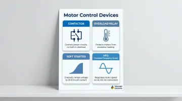
This layer handles starting, stopping, and speed regulation for electric motors:
- Contactors: Electromechanical switches that control power circuits, typically lacking built-in overload protection
- Overload relays: Protect motors and branch-circuit conductors against excessive heating
- Soft starters: Limit inrush current during motor startup by gradually ramping voltage, reducing mechanical and electrical stress
- Variable frequency drives (VFDs): Regulate motor speed by converting AC to DC, then inverting back to AC with modulated frequency and voltage
For demanding applications requiring smooth motor control and IEEE 519 harmonic compliance, component selection directly impacts panel performance. ValuAdd's VFDs use H-Bridge multi-level technology delivering less than 8% THDv and 5% TDDi, while their medium voltage soft starters (ranging from 2.3kV to 15kV, 110A to 1200A) provide Class E2 load break compliance for critical installations.
Control & Automation Components
Programmable Logic Controllers (PLCs), I/O modules, and Human-Machine Interfaces (HMIs) monitor and automate processes. PLC racks and I/O terminals should be placed in the lower section of the panel, away from high-heat power components. Ethernet switches and communication hardware require physical separation from high-power wiring—Rockwell Automation recommends at least 3 inches (0.08m) spacing from Category-1 power conductors in contiguous metallic wireways to prevent EMI-related signal degradation.
Protection & Safety Devices
Safety circuits protect personnel and equipment:
- Emergency stop switches and safety relays must use dedicated, physically separated terminal blocks
- Dual-channel wiring routed away from standard control circuits provides redundancy per ISO 13849-1 and IEC 62061 requirements
- Surge Protective Devices (SPDs) are now mandatory under NFPA 70 Article 670.6 and NFPA 79 7.8.1—missing surge protection is one of the costliest oversights in panel design
- Fuses and circuit breakers provide overcurrent protection
Structural and Wiring Hardware
DIN rails, terminal blocks, wiring ducts, and enclosures form the panel's structural backbone. DIN rail capacity should include 15-20% spare space for future additions. The NEC limits wireway fill to 20% of interior cross-sectional area to prevent overheating and ensure proper wire management.
Enclosure selection must match the environment:
- NEMA 12: Standard for indoor manufacturing, protects against circulating dust, lint, fibers, and dripping non-corrosive liquids
- NEMA 4X: Required for washdown or corrosive areas, protects against windblown dust, hose-directed water, and corrosion
Electrical Panel Layout & Physical Design Best Practices
Layout design should be approached from the perspective of the maintenance technician troubleshooting the panel at 2 AM during a production emergency. Every decision about component placement, labeling, and wire routing either speeds up or slows down fault diagnosis.
Schematic and BOM First
Layout work must begin with a complete schematic covering power distribution, I/O, and control circuits, plus a detailed Bill of Materials. Physical layout drawings should develop alongside schematics—not after—to catch spacing conflicts and clearance violations before assembly. Industry-standard tools include AutoCAD Electrical for high-volume standardized panels, EPLAN Electric P8 for complex OEM applications, and SOLIDWORKS Electrical when deep 3D mechanical integration is required.
Component Grouping Logic
Follow this three-layer hierarchy:
- Main disconnect, bus bars, and branch breakers at the top (high-voltage power zone)
- Motor control and drives in the mid-section, positioned near ventilation to manage heat dissipation
- PLC racks, I/O terminals, and signal devices at the bottom, away from heat sources
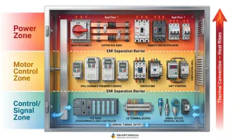
AC and DC circuits must be physically separated with barriers or partitions to minimize EMI and short-circuit risk. Heat-generating devices like VFDs and power supplies must be placed closest to cooling equipment—most electronic components begin derating above 40-50°C.
Internal Spacing and the 80% Rule
The 80% rule requires panels and circuit breakers be loaded to no more than 80% of rated capacity. Under NEC Article 100, a continuous load runs for 3 hours or more. NEC 210.20(A) and 215.2(A)(1) require overcurrent protective devices and conductor ampacity sized at 100% of noncontinuous load plus 125% of continuous load—mathematically equivalent to limiting continuous loads to 80% of breaker rating.
Reserve approximately 20% of enclosure area as spare space for future modifications. Follow manufacturer minimum clearance requirements for high-voltage components.
The 36-Inch Clearance Rule
NEC Article 110.26(A)(1) and OSHA 29 CFR 1910.303(g)(1) mandate at least 36 inches of clear working space in front of electrical panels operating at 0-600V. This space allows safe access for operation, maintenance, and emergency response. The clearance extends from floor to 6.5 feet height and cannot be used for storage.
Violating this rule creates inspection failures and OSHA compliance issues. Panel placement during facility planning must account for this before installation.
Labeling and Documentation Standards
Every wire, terminal, and component must carry a unique label matching the schematic exactly. Common conventions include:
- Address-based labels for PLC I/O (e.g., "I:1/0" for input module 1, point 0)
- Line-number-based labels for non-PLC wiring
- Voltage prefix labels for power distribution (e.g., "480V-L1")
Accurate documentation—including schematic diagrams, BOM with part numbers, panel layout drawings, and SCCR calculations—must be delivered with every panel. This documentation directly determines how quickly faults can be diagnosed after commissioning.
Wiring, Grounding & Thermal Management
Wire management and thermal planning have direct consequences for panel performance, safety, and the cost of future service calls — get either wrong and you're building in problems from day one.
Wire Routing and Management
Wires should always run horizontally or vertically using cable trays and wiring ducts—never diagonally, never cable ties alone. Power wiring and signal/communication wiring (CAN bus, Profibus, analog signals) must run in separate ducts. Electromagnetic noise from high-power cables degrades transmission in control wiring.
Stranded wire is preferred over solid for industrial panels due to flexibility and lower heat generation. IEC 60228 defines conductor classes, with Class 5 and Class 6 stranded copper being standard for industrial control wiring.
Use tubular tin-plated copper ferrules (standardized under DIN 46228) on all stranded wire terminations to prevent stray strands and nuisance faults. UL 508A 29.3.6 permits ferrules provided they're sized appropriately and crimped with manufacturer-recommended tools.
Grounding Best Practices
Poor grounding is a leading cause of control device failure and unexplained electrical noise. Requirements include:
- Dedicated grounding bus bar accessible to all grounding conductors
- Single-point (star) grounding topology to eliminate ground loops
- Grounding conductors routed separately from power lines
- Compliance with NFPA 79 and UL 508A grounding/bonding requirements that vary by machine type
Thermal Management
Heat is the primary cause of premature component failure in enclosed panels. Every VFD, power supply, PLC, and relay dissipates heat that must be actively managed. Calculate heat load by:
- Summing component power dissipation values (in watts) from datasheets
- Factoring in ambient temperature at the installation site
- Determining required cooling method
Cooling options include:
- Filtered fans for NEMA 12 enclosures in clean, low-dust environments
- Air-to-air heat exchangers for sealed enclosures where contamination is a concern
- Panel air conditioners for high-heat loads or elevated ambient temperature installations
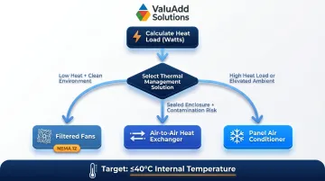
Most electronic components begin derating above 40-50°C, making 40°C the design target for maximum internal temperature.
Service Loops and Spare Capacity
Thermal planning addresses today's load — service loops address tomorrow's maintenance. Loops at entry and exit points provide critical flexibility for future component replacement. Replacement parts may come with shorter leads—adequate slack managed neatly within wireways prevents issues. Never cut wires to exact length in industrial panels.
Leave spare terminal blocks, spare I/O points, and spare duct space as standard practice for panels expected to serve 15-20+ year machine lifespans.
Design Compliance Standards to Know
Compliance is not a final checkbox—it must be designed in from the start. Three primary North American standards govern industrial panel design.
UL 508A
UL 508A is the primary standard for industrial control panel construction in North America, covering:
- Enclosure selection and NEMA ratings
- SCCR calculation methodology (Supplement SB)
- Wire ampacity requirements
- Spacing between live parts
- Required nameplate marking
SCCR must be calculated for the entire panel assembly, not just individual components. Underestimating available fault current creates genuine safety hazards. Panels must be permanently marked with their SCCR per 409.110(4).
NFPA 79 and NEC
NFPA 79 governs the complete electrical system on industrial machines, including:
- Control circuit protection
- Emergency stop circuit design
- Disconnecting means and interlocks
- Grounding and bonding
- Documentation requirements
NEC Article 409 applies once the panel is installed, requiring that available fault current at the installation point not exceed the panel's marked SCCR. For equipment going to international markets, IEC 61439 applies and should be designed for from the start to avoid rework.
IEEE 519 and NEMA Ratings
Grounding and bonding requirements under NFPA 79 connect directly to power quality concerns. IEEE 519 sets harmonic distortion limits for power systems—particularly relevant when panels include VFDs, which generate harmonics that can affect other connected equipment:
| Bus Voltage at PCC | Individual Harmonic Limit | THD Limit | |--------------------|---------------------------|-----------|\n| ≤1.0 kV | 5.0% | 8.0% | | 1-69 kV | 3.0% | 5.0% |
NEMA enclosure ratings must match the installation environment—a NEMA 12 enclosure suits most indoor industrial settings, while NEMA 4X is required where washdown or corrosion is a factor. When sourcing components, look for products with documented compliance: for instance, VFDs rated at <8% THDv and <5% TDDi satisfy IEEE 519 thresholds out of the box, reducing the harmonic analysis burden during design.
Common Design Mistakes and How to Fix Them
The same panel design mistakes show up across facilities and industries — water treatment plants, manufacturing floors, oil and gas installations. Nearly all of them trace back to decisions made early in the design phase that get expensive fast once the panel is in the field.
Undersized Enclosures
Cramming components into the smallest possible enclosure leaves no room for heat dissipation, wire management, or future modifications. It's a common cost-cutting move that routinely creates more expensive problems downstream.
Size the enclosure based on the full component list plus 20% spare space. Run heat load calculations before finalizing dimensions — not after. If your calculation shows 800W dissipation, size cooling equipment for 1000W to keep a working margin.
Missing or Inconsistent Wire Labeling
Unlabeled, mislabeled, or inconsistently labeled wires mean every future service call starts with reverse-engineering the panel. On a complex build, that can add hours to routine troubleshooting.
Enforce a labeling standard at the design stage, then verify label-to-schematic accuracy during build QC. The delivered documentation package should include a wire schedule covering every wire number, source terminal, destination terminal, and wire gauge.
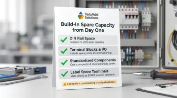
No Spare Capacity Designed In
When every DIN rail, wireway, and terminal strip is filled to capacity at commissioning, any future modification effectively becomes a rebuild. This is one of the costliest design shortcuts to fix after the fact.
Build capacity headroom in from the start:
- Reserve 15–20% spare DIN rail space
- Include spare terminal blocks and I/O points at commissioning
- Standardize components across machines so one spare parts kit covers multiple panels
- Label all spare terminals clearly as "SPARE" to avoid confusion during troubleshooting
Pro Tips for Designing Industrial Electrical Panels
These four principles consistently separate panels that age well from ones that become maintenance headaches within a few years.
Design for the maintenance technician first. Logical component grouping, clear labels, and an accessible layout reduce troubleshooting time far more than any diagnostic tool. A well-organized panel lets technicians trace circuits visually—no constant cross-referencing of schematics required.
Standardize across machines wherever possible. Consistent wire colors, terminal block brands, PLC families, and labeling conventions across a facility multiply the value of every training hour and every spare part stocked. When a technician understands one panel, they understand all of them.
Treat documentation as a deliverable, not an afterthought. A panel shipped with accurate schematics, a BOM, SCCR calculations, and thermal analysis is worth more to the facility over its service life than one without. Build documentation review into the project sign-off checklist—and update it whenever the panel changes.
Bring in a specialist early for high-stakes designs. Medium voltage systems, complex safety architectures, and unusual environments (explosive atmospheres, extreme temperatures) reward early involvement of a certified panel engineer or the component manufacturer's application team. Catching a design conflict before fabrication is far less costly than correcting it afterward.
Frequently Asked Questions
What is the 80% rule for electrical panels?
The 80% rule requires panels and circuit breakers to be loaded to no more than 80% of rated capacity under continuous load conditions, preventing overheating and ensuring compliance with NEC Article 210.20(A) and 215.2(A)(1). The remaining 20% provides a safety margin and headroom for future load additions.
What is the 36 inch rule for electrical panels?
NEC Article 110.26 requires a minimum of 36 inches of clear working space in front of electrical panels to allow safe access for operation, maintenance, and emergency response. Violating this rule creates inspection failures and OSHA compliance issues—this clearance cannot be used for storage.
What are the 7 parts of an electrical wiring plan?
A complete electrical wiring plan includes: Bill of Materials (BOM), functional diagram, power distribution diagram, I/O wiring diagram, control circuit schematic, enclosure/backpanel layout drawing, and wire schedule/labeling plan.
What certifications should an industrial electrical panel have?
North American panels must comply with UL 508A, NFPA 79, and NEC Article 409; international markets also require IEC 61439. NEMA enclosure ratings (4X for wet/corrosive environments, 12 for industrial dust) must match the installation site conditions.
How do you calculate heat load for an electrical panel?
Sum the power dissipation values (in watts) from each component's datasheet, then factor in ambient installation temperature to determine whether passive ventilation, a heat exchanger, or active cooling is needed—targeting a 40°C maximum internal temperature to prevent component derating.
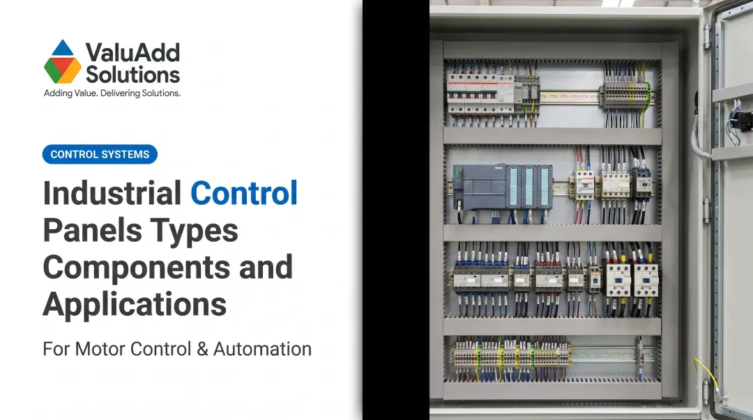
What is the difference between a PLC control panel and a motor control center?
A PLC panel is built around Programmable Logic Controllers to automate and monitor process inputs/outputs. A Motor Control Center (MCC) is a dedicated assembly for starting, stopping, and protecting multiple motors from one centralized location. Industrial facilities often integrate both into a single panel architecture.