Introduction
Panel builders and system integrators face a harsh reality: a well-designed electrical enclosure can mean the difference between reliable uptime and costly unplanned shutdowns. Yet industry data shows that most failures trace back to poor hardware selection or disorganized cable management, not faulty electrical components. When a VFD trips unexpectedly or a NEMA-rated enclosure fails in a washdown environment, the root cause is rarely the drive itself. More often, it's inadequate clearance spacing, overfilled wire ducts, or corroded mounting hardware that compromises system integrity.
This guide covers the full spectrum of panel hardware—DIN rails, terminal blocks, busbars, backplates—and cable management solutions including wire ducts, raceways, and routing best practices that form the structural backbone of any industrial control panel. These components determine whether your panel survives five years or twenty in demanding environments.
TLDR:
- DIN rail and terminal block selection affects component compatibility and safety
- Proper busbar sizing prevents thermal hazards and ensures safe power distribution
- Wire duct fill ratio (maximum 40%) determines cable protection and heat dissipation
- Separate power and control wiring physically to prevent EMI-related failures
- Match NEMA Type 12 or 4X enclosures to your specific environmental hazards
Core Panel Hardware Components Inside an Electrical Enclosure
DIN Rails: The Foundation for Component Mounting
DIN rails serve as the primary mounting platform for switchgear and controlgear, governed by the IEC 60715:2017 standard. Rail selection affects three critical factors: component compatibility, load-bearing capacity, and ease of reconfiguration during maintenance.
| DIN Rail Type | Dimensions | Primary Application |
|---|---|---|
| Top-Hat (Symmetric) | 35mm x 7.5mm / 15mm | Universal industrial components, PLCs, breakers |
| G-Type (Asymmetric) | 32mm x 15mm | Legacy systems, high-vibration environments |
| Miniature | 15mm x 5.5mm | Space-constrained compact terminals |
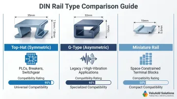
Standard 35mm galvanized steel DIN rails provide a short-time withstand current of 1.92 kA per second — equivalent to 16mm² copper wire — per IEC 60947-7-2. Load capacity is a real selection variable, not a checkbox. For corrosive environments like chemical processing or coastal installations, stainless steel rails (SS 304 or SS 316) prevent rust and maintain structural integrity over decades of service.
The 35mm symmetric top-hat rail is the universal standard compatible with the widest range of devices. Unless you're maintaining legacy equipment or working in extreme space constraints, specify 35mm rails to maximize component interchangeability.
Terminal Blocks: Organized Connection Points
Terminal blocks for industrial copper conductors are governed by IEC 60947-7-1:2025, with protective conductor (PE) blocks covered under IEC 60947-7-2:2009. These components provide the organized transition between external field wiring and internal panel wiring.
Four essential terminal block types:
- Feed-through blocks — Standard circuit connections for signal and power wiring
- Ground/PE blocks — Bonding to DIN rail for equipment grounding continuity
- Disconnect/test blocks — Circuit isolation for maintenance and CT testing without disturbing wiring
- Fused blocks — Integrated overcurrent protection at the terminal point
Choosing the wrong block type creates troubleshooting risks. A panel without dedicated disconnect blocks forces technicians to remove wiring during testing, introducing reconnection errors. Ground blocks without proper bonding to the rail violate UL 508A Section 14.3 requirements and compromise personnel safety.
Busbars: Power Distribution Backbone
Busbars — both neutral and ground — establish the low-impedance path for distributing power and maintaining a safe ground reference throughout the panel. IEC 61439 permits design rule verification of busbar short-circuit withstand strength through calculation or comparison with tested reference designs.
Undersized busbars create thermal hazards. When two sources feed from opposite ends of a busbar, current from both can stack, overheating the conductor if not properly rated. This is especially critical in panels with multiple power feeds or solar PV backfed breakers.
Addressing these sizing requirements, ValuAdd's busbar portfolio covers rigid copper bars for primary and secondary distribution — heights from 20mm to 160mm, thicknesses from 5mm to 10mm — alongside flexible Isoflexx® laminated busbars with cross-sections from 21.6mm² to 1200mm². Both product lines are IEC-certified for the current-carrying capacity and thermal stability that high-ampacity industrial applications demand.
Backplates and Sub-Panels
Backplates (mounting panels or sub-panels) provide the structural mounting surface that allows pre-assembly of components before installing into the enclosure. This dramatically reduces installation time and enables quality control testing before deployment.
Standard industrial backplates are typically constructed from 11 gauge (3.0mm) sheet steel with zinc-plated finish for durability and conductivity. UL 508A Section 14.3 requires that equipment grounding terminals have electrical continuity with all metal parts via metal-to-metal contact or an internal bonding conductor.
Thinner-gauge steel (14ga or 16ga) may seem acceptable initially but flexes under load, loosening mounted components over time. In corrosive environments, zinc plating alone may not suffice — consider powder coating or stainless steel backplates for water treatment or chemical processing applications.
Supplementary Hardware
Panel feet, standoffs, grounding studs, cable glands, and locking hardware are routinely treated as afterthoughts. In practice, they're among the most common sources of ground loops, ingress failures, and vibration-related loosening in industrial environments.
IEC 62444:2010 governs cable gland requirements, and manufacturers specify exact tightening torques for good reason — for example, 6.0 Nm for M20 plastic glands. Over-tighten and you damage cable insulation. Under-tighten and you compromise the enclosure seal, negating your investment in NEMA 4X construction.
Cable Management and Wire Routing Solutions
Wire Duct Types and Applications
Wire duct (also called cable duct or cable raceway) is the primary cable management tool inside enclosures. The four main types each serve distinct purposes:
| Duct Type | Characteristics | Best Application |
|---|---|---|
| Narrow Slot (Type F) | High finger density | High-density terminal blocks; reduces wire fanning |
| Wide Slot (Type G) | Greater sidewall rigidity | General purpose; accommodates wide wire bundles |
| Solid Wall (Type FS) | Unslotted, fully enclosed | Straight runs without breakouts; protects from dust |
| Round Hole (Type D) | Flush cover, round exits | Positioning wires at various heights when transitioning |
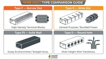
Selection guidance: Narrow slot ducts work well adjacent to terminal blocks with high connection density, where you need frequent wire breakouts every few inches. Wide slot ducts handle thicker bundled power wiring where sidewall rigidity prevents deformation under cable weight. Solid wall ducts suit straight vertical or horizontal runs in dusty environments where protection outweighs the need for frequent access.
Cable Ties, Lacing, and Retention Methods
Cable ties provide supplementary retention outside wire ducts, but over-tightening is a common failure mode. Manufacturers recommend tensioning tools with preset limits—HellermannTyton's EVO series tools offer settings from 4 to 37 lbs—to prevent insulation crush, which causes signal issues on control cables near VFDs or data wiring.
For serviceable panels, the retention method you choose directly affects long-term maintenance cost. Three options cover most applications:
- Hook-and-loop fasteners (VELCRO® ONE-WRAP® style) — enable adds, moves, and changes without cutting and replacing ties
- Standard zip ties — suited for permanent installations where wiring won't be modified
- Identification cable ties with external marking plates — keep conductor labels visible without shrink tubing, speeding up troubleshooting
Standard zip ties are cost-effective but create rework risk: every modification means cutting ties and re-tensioning, which introduces the same insulation crush hazard you were trying to avoid.
ValuAdd offers multiple cable tie configurations including identification cable ties with external marking plates, which simplify troubleshooting by keeping conductor labels visible without shrink tubing.
Cable Trays vs. Enclosed Wire Ducts
Cable trays and wire ducts serve different purposes and are governed by different standards—cable trays by NEC Article 392 and IEC 61537:2023, wire ducts by panel builder standards like UL 508A.
Key distinction: Cable trays are open support systems for routing cables across facilities or between enclosures, offering easy access and heat dissipation for high-current power cables. Enclosed wire ducts protect sensitive control or communication wiring from EMI within the same enclosure where power cables are present.
Use cable trays for inter-panel or facility-level runs; use wire ducts for intra-panel organization where EMI protection and dust exclusion are priorities.
Cable Labeling Systems
NEC Article 409 and UL 508A mandate systematic labeling of all conductors, terminal blocks, and devices within industrial control panels. Unlabeled panels increase fault diagnosis time and introduce wiring errors during maintenance — both carry real cost consequences in production environments.
Three labeling methods:
- Heat-shrink markers for permanent wire identification
- Adhesive labels for terminal blocks and devices
- Wire ferrules for termination points requiring frequent changes
Choose your labeling system before assembly begins. Retrofitting labels on completed panels is time-consuming and often incomplete, leaving critical circuits unmarked during emergency troubleshooting.
Fill Ratio Management
UL 508A sets a 40% maximum fill ratio for continuous wireway runs. Overfilled ducts trap heat (tightly packed cables can't dissipate it effectively), impede wire pulling during maintenance, and put panels out of compliance.
Calculate fill ratio before selecting duct size: total the cross-sectional area of all cables in a given section, divide by the duct's internal area, and confirm you're under 40%. Build in margin for future additions — a duct at 38% fill today becomes a problem the next time sensors get added.
Enclosure and Mounting Hardware Selection
Enclosure Types and NEMA Ratings
NEMA 250-2020 defines enclosure types for non-hazardous locations. For industrial environments with washdown, dust, or corrosive exposure, enclosure selection is a safety and compliance decision.
| NEMA Type | Environment | Approximate IP Equivalent |
|---|---|---|
| Type 12 | Indoor; protects against falling dirt, dust, lint, and light water splashing | IP54 |
| Type 4 | Indoor/outdoor; protects against rain, splashing, and hose-directed water | IP66 |
| Type 4X | Type 4 protection plus corrosion resistance for washdown or coastal areas | IP66 |
Material selection prevents failure. Using standard mild steel in a chloride-laden coastal or chemical environment causes rapid corrosion. NEMA 4X mandates stainless steel or fiberglass-reinforced polyester (FRP) construction for corrosive environments — the material specification is a structural integrity requirement, not a recommendation.
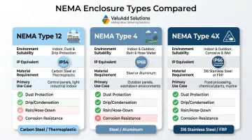
ValuAdd carries NEMA Type 4X and Type 12 enclosures suited for oil and gas, water treatment, and other demanding industrial environments.
Panel Cooling and Thermal Management
Heat is the primary cause of electronic failure. A 10°C temperature increase relative to maximum operating temperature halves component service life and doubles the failure rate.
Calculate your heat load: The maximum temperature increase inside an uncooled enclosure is calculated as (Ti-Tu) = Qv / (k×A), where Ti is internal temp, Tu is ambient temp, Qv is internal heat dissipation, k is the heat transfer coefficient, and A is the effective surface area.
Thermal management options:
- Vented panels for low-heat applications in clean environments
- Fan-and-filter kits for active cooling with filtered air intake
- Heat exchangers that cool without introducing external air
- AC units for high-heat-density panels (multiple VFDs or high-power drives)
VFDs, power supplies, and contactors generate significant heat. Calculate total heat dissipation across all components, add a 20% margin, and select cooling accessories that keep internal temperature within component ratings.
VFD derating is a related concern. For example, Rockwell PowerFlex 750 drives require derating when operating above 40°C — factor this into your thermal budget before finalizing enclosure sizing.
Door Hardware and Accessibility
Door hardware — quarter-turn latches, door-mounted HMI brackets, interlock mechanisms — must allow rapid operator access while preventing unauthorized entry and maintaining the enclosure's environmental rating. UL 508A requires captive-type fasteners to secure doors while maintaining environmental ratings.
For unmanned installations or hazardous areas, verify that your hardware selection meets these constraints:
- Lockable latches prevent unauthorized access without blocking emergency shutdown
- Door-mounted HMI brackets must preserve the enclosure's NEMA rating when installed
- Any mounting penetration requires proper sealing — an unsealed penetration voids the NEMA rating
Motor Control and Drive Hardware Integration
VFD and Soft Starter Mounting Requirements
Variable frequency drives and soft starters demand strict clearances for heat dissipation. Siemens SINAMICS G120X drives require 80mm lateral clearance and 100mm front clearance—violate these specifications and you'll experience thermal derating or premature failure.
Smaller VFDs (typically up to 5-7 HP depending on manufacturer) support DIN rail mounting for compact installations. Larger drives require panel mounting with dedicated fasteners — and ValuAdd's VFDs and soft starters are engineered specifically for panel integration in demanding industrial environments, with defined mounting and clearance specs that must be followed during layout.
VFD output cables generate electromagnetic interference that causes false trips, communication errors, and sensor drift when routed near PLC I/O or instrumentation wiring. Per Siemens SINAMICS documentation, maintain ≥25cm side clearance between EMI zones as a minimum separation requirement.
Contactors, Relays, and Motor Starters
These DIN rail-mounted control devices, governed by IEC 60947-4-2 standards, require separate routing for coil wiring versus load wiring to prevent control circuit noise and nuisance tripping.
Mixed routing of coil wiring and load wiring is a common installation mistake with real consequences:
- Route contactor coil wiring (24VDC or 120VAC control) in dedicated wire ducts
- Keep load wiring (motor power circuits) in separate ducts entirely
- Mixed routing introduces noise that causes relay chatter, missed PLC inputs, or false alarms
Power Distribution Blocks
UL 1953 Listed power distribution blocks provide organized AC and DC supply voltage distribution within panels, meeting UL 508A minimum spacing requirements (1-inch through-air, 2-inch over-surface) for feeder circuits.
Spliced wiring creates troubleshooting nightmares. Distribution blocks provide labeled, organized connection points with Short-Circuit Current Ratings up to 200 kA — maintaining panel safety over the equipment's full service life.
When a technician needs to trace a 24VDC fault three years after commissioning, clear distribution block connections save hours compared to hunting through bundled splices.
Best Practices for Panel Organization and Long-Term Maintainability
Physical Separation Between Power and Control Wiring
UL 508A and component manufacturers recommend routing power wiring—especially VFD output cables—in dedicated wire ducts physically separated from control, signal, and communication wiring.
Minimum separation: Route control wiring on the opposite side of the panel from power wiring. When separation distance is limited, use shielded cable for sensitive control circuits. Input power wiring and motor wiring must not be run in the same conduit.
Inadequate wiring separation is a common source of field problems. VFD output cables run adjacent to PLC I/O wiring cause:
- False trips and sensor drift from electromagnetic interference
- Erratic analog readings as signal cables pick up noise
- Intermittent Ethernet/IP and Modbus communication failures
All of these stem directly from wiring separation shortcuts during panel assembly.
Logical Component Layout Planning
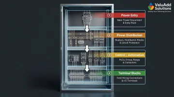
Establish consistent layout conventions before any hardware is installed:
- Power entry at top — Main disconnect near entry point
- Power distribution next — Busbars, distribution blocks, circuit protection
- Control/automation components in middle — PLCs, drives, relays, contactors
- Terminal blocks at bottom — Field wiring connections
This top-to-bottom power flow mirrors electrical logic and reduces wiring complexity. UL 508A and NFPA 79 dictate panel layout must support clean separation between safety-rated wiring, power circuits, and standard control wiring.
When every panel follows the same layout convention, technicians troubleshoot faster and assembly errors decrease. A manufacturer building 20 identical panels per month benefits substantially from standardized component placement.
Strain Relief and Cable Entry Management
Cable glands, conduit knockouts, and sealing inserts provide structural protection at cable entry points. Poorly managed cable entry points are a primary cause of enclosure ingress failures in wet or dusty environments, completely negating your investment in NEMA-rated construction.
Cable glands must be installed with correct tightening torque (per manufacturer specifications) to achieve Category A strain relief per IEC 62444 and maintain the enclosure's IP rating. Use the correct gland size for cable diameter — oversized glands cannot seal properly, and undersized glands damage cable insulation.
Planned Spare Capacity
Leave deliberate margin for future modifications:
- Spare DIN rail space (10-20% empty rail length)
- Extra wire duct fill capacity (target 30-35% fill, not 40%)
- Spare circuit/terminal positions (10% additional capacity)
This is especially critical for panels in facilities where future expansion is likely — adding sensors, expanding automation, or integrating new equipment. Panels built with zero margin require expensive modifications: new wire ducts, relocated components, or complete panel replacements.
A panel built with 15% spare capacity costs 5-8% more upfront but reduces future modification costs by 60-70%. For facilities planning multi-year automation expansions, that margin isn't optional — it's built-in insurance.
Frequently Asked Questions
What are the 80% and 120% rules for electrical panels?
The 80% rule (NEC 210.20(A)) limits continuous loads to 80% of a breaker's rated ampacity to prevent thermal overload. The 120% rule (NEC 705.12(B)(3)(2)) permits solar PV backfed breakers to push bus utilization up to 120% of rated capacity, provided that breaker is installed at the opposite end from the main breaker.
What are the main components of an electrical panel?
Core components include:
- Main breaker and branch circuit breakers
- DIN rails, busbars (neutral and ground), and terminal blocks
- Wire duct, power supply, relays/contactors, and enclosure/backplate
Industrial control panels extend this base with motor drives, PLCs, HMIs, and communications hardware.
What is the difference between wire duct and cable tray in an electrical enclosure?
Wire duct is an enclosed plastic raceway used inside enclosures to organize and protect wiring between components. Cable tray is an open ladder or solid-bottom support system for larger wire runs across facilities or between enclosures. Wire duct suits intra-panel organization; cable tray suits facility-level routing.
What NEMA rating is required for industrial electrical enclosures?
NEMA Type 12 is standard for indoor industrial environments with dust and dripping liquids. NEMA Type 4X adds corrosion resistance and is required for washdown environments or outdoor/coastal installations. Match the enclosure NEMA rating to environmental hazards at the installation site.
How do you select the right DIN rail for a control panel?
The 35mm symmetric DIN rail is most universal and compatible with the widest range of components. G-type and mini rails suit specific legacy or compact applications. Confirm rail material (steel vs. stainless), length, and current-carrying requirements against component manufacturer specifications.
How should power and control cables be separated inside an electrical enclosure?
Route power wiring — particularly VFD output cables — in dedicated wire ducts separated from control, signal, and communication wiring. When physical separation is limited, use shielded cable for sensitive circuits and follow both NEC requirements and component manufacturer guidelines.