
A competent in-house automation engineer or qualified system integrator with experience in PLC communication and industrial panel installation can handle this process. However, first-timers should not attempt it without reviewed electrical drawings and knowledge of relevant safety standards, including NFPA 70E and UL508A. NFPA 70E defines a "qualified person" as one who has demonstrated skills and knowledge related to the construction and operation of specific electrical equipment and has received safety training to identify and avoid hazards. Qualification is task-specific and requires refresher training at intervals not exceeding 3 years.
This guide walks through the complete process—from pre-installation prerequisites to final validation—covering both the physical setup of the touch panel and the programming steps required to connect it to a control system.
Key Takeaways
- Setting up an industrial HMI involves physical mounting/wiring and software programming—both must be executed correctly for reliable operation
- Verify 24VDC power compatibility, IP rating requirements, and PLC protocol support before purchasing
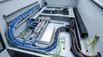
- Physical installation covers panel cutout prep, mounting, power wiring, grounding, and communication cable connection
- Programming requires configuring communications, building a PLC-linked tag database, and designing clear operator screens with alarms
- Complete communications, screen, and alarm validation before commissioning for production use
Setup and Programming Guide for Industrial HMI Touch Panels
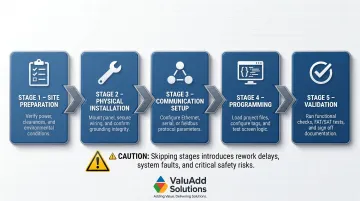
The setup process moves through five stages: site preparation → physical installation → communication setup → programming → validation. Rushing or skipping any stage causes rework and creates real safety and data integrity risks. For a single-panel HMI connected to one PLC, expect a half-day to full day of work — electrician and automation engineer coordinating together.
Prerequisites and Safety Considerations
Before starting, verify these critical specifications:
Power and environmental compatibility:
- Confirm the HMI's supply voltage matches available panel power—typically 24VDC
- Verify the display's IP rating suits the installation environment (IP65 minimum for most production environments; IP66/IP68 for wash-down or submersed-risk areas such as water treatment or food processing facilities)
- Confirm operating temperature range matches the installation site
For demanding environments, ValuAdd's industrial touch panels carry IP65, IP66, and IP68 ratings. For example, the CM-eXT2-10W-RH-DF operates reliably from -20°C to +70°C with IP68 protection, making it suitable for outdoor installations and extreme thermal environments.
Communication protocol verification: Verify that the HMI supports the PLC brand and communication protocol being used:
- EtherNet/IP for Allen-Bradley (Rockwell Automation holds approximately 22% global PLC market share)
- PROFINET for Siemens (Siemens leads with approximately 30% global PLC market share)
- Modbus TCP for multi-vendor setups
With protocols confirmed, address these safety requirements before touching any wiring:
- Panel must be de-energized and locked out/tagged out before any wiring work begins
- HMI must not be powered until all wiring connections are inspected
- Enclosure cutout dimensions must match the manufacturer's specs exactly — a poor fit risks ingress protection failure
Compliance verification: Confirm that the installation environment's classification (hazardous location vs. general industrial) determines whether additional certifications are required on the HMI unit. Check for:
- UL Listed compliance
- CE certification
- NEMA Type 4X or 12 compliance
- FCC certification
Once prerequisites are verified, gather everything needed before the installation window opens.
Tools and Equipment Required
Installation tools:
- Panel cutout tools (jigsaw or nibbler for sheet metal)
- Torque screwdriver calibrated to manufacturer's mounting clamp specifications
- Multimeter for voltage verification before power-on
- Deburring tool for cutout edge preparation
Connection materials:
- Ethernet cable (shielded Cat5e or Cat6) and crimping tools
- 24VDC power supply and wiring terminals
- Ferrite cores (for high-EMI environments near VFDs or motor starters)
Programming essentials:
- HMI vendor's programming software installed on a laptop
- USB or Ethernet cable for project upload
- PLC's current program and I/O address list (without this, tag mapping cannot begin)
How to Set Up an Industrial HMI Touch Panel (Physical Installation)
Step 1 — Prepare the Enclosure Cutout
The cutout must be made to the manufacturer's specified dimensions found in the product datasheet. For example, the CM-eXT2-12W-R-DE requires a panel cutout size of 305 x 212 mm.
Critical requirements:
- Cut edges must be deburred and cleaned to avoid damaging the gasket seal
- Permissible deviation from plane: ≤ 0.5 mm
- Surface roughness in seal area: ≤ 120 µm (Rz 120)
- Panel material thickness: typically 2 to 6 mm
A rough or oversized cutout will compromise the ingress protection rating regardless of panel quality. Manufacturers explicitly void warranties for improper mounting—Siemens warns that the IP degree of protection is only guaranteed if the mounting gasket fits completely to the mounting cut-out.
Step 2 — Mount the HMI in the Enclosure
Insert the panel from the front of the enclosure and secure the mounting clamps evenly from behind in the sequence specified by the manufacturer (usually alternating corners, as noted in the installation drawing).
Rockwell PanelView terminals, for example, require mounting clip screws tightened to 0.90 to 1.1 N·m (8 to 10 lb·in). Uneven torque or over-tightening distorts the display bezel and breaks the gasket seal. Under-tightening creates gaps that allow water and dust ingress.
Step 3 — Wire the Power Supply
24VDC is the industry-standard supply voltage for most industrial HMI panels. The positive and negative supply must be wired to the correct terminals as labeled on the unit.
Power supply requirements:
- Use SELV (Safety Extra-Low Voltage) or PELV (Protective Extra-Low Voltage) supply per IEC 60364-4-41
- Connect DC ground to the enclosure's PE (protective earth) ground bus
- Wire sizing: power circuit conductors no smaller than 14 AWG per UL 508A
Polarity and inrush considerations: Reversing polarity will damage the unit and void the warranty, though most modern units include reverse polarity protection. Separately, inrush currents at power-ON can reach 2A or higher — enough to cause voltage drops that affect other devices sharing the same supply rail.
Step 4 — Connect the Communication Cable
For Ethernet-based communication, run a shielded Cat5e or Cat6 cable from the HMI's Ethernet port to the network switch or directly to the PLC's Ethernet port.
EMI mitigation requirements:
- Separate power cables from signal cables by at least 200 mm to prevent cross-coupling
- Use shielded cables in high-EMI environments (VFD panels, motor control centers)
- Connect shields over a large surface area at both ends using designated shield clamps
- Add ferrite cores to cables running near sources of high EMI
Unshielded cables in high-EMI environments are a frequent source of communication noise faults. For serial connections (RS-232/RS-485), verify the cable pinout against the manufacturer's wiring diagram before connecting — pin assignments vary between manufacturers and incorrect wiring will prevent communication.
Step 5 — Power On and Confirm Boot
After a final visual inspection of all wiring, restore power and confirm the HMI boots to its default startup screen or configuration menu. Check that no fault indicators are present on the unit.
Once the unit boots cleanly with no faults, the physical installation is complete. With hardware confirmed operational, the next phase covers software configuration and programming the HMI to communicate with your PLC.
How to Program an Industrial HMI Touch Panel (Step-by-Step)
HMI programming is primarily a configuration and screen development process using vendor-supplied software, not traditional code writing. That said, errors in tag addressing, read/write permissions, or communication parameters can cause data display failures and process control faults that are genuinely difficult to trace after the fact.
Step 1 — Configure Communication Settings
Open the HMI programming software and create a new project. Common platforms include:
- FactoryTalk View Studio for Allen-Bradley PanelView terminals
- TIA Portal for Siemens SIMATIC HMIs
- EasyBuilder Pro for Weintek units
- C-more Programming Software for AutomationDirect panels
Add the PLC as a connected device by selecting the correct communication driver (e.g., EtherNet/IP, PROFINET, Modbus TCP). Enter the PLC's IP address and confirm the HMI and PLC are on the same subnet.
Critical checkpoint: A protocol mismatch or incorrect IP subnet at this stage is the most common reason HMIs fail to communicate with the PLC after initial setup. Both devices must be on the same subnet (e.g., 192.168.1.x with subnet mask 255.255.255.0).
Step 2 — Build the Tag Database
Create a tag (variable) for each PLC data point that the HMI needs to read or write:
- Machine status bits
- Setpoints
- Process values
- Fault flags
Use consistent tag naming with equipment prefixes — this makes troubleshooting far faster when a tag misbehaves months after commissioning:
- Pump1_RunStatus
- Pump1_SpeedSetpoint
- Pump1_Fault
- Tank2_LevelPV
Read/write permissions: Configure all PLC input data points as read-only in the HMI. If both devices attempt to write to the same memory address simultaneously, the result is a data conflict that can corrupt process logic with no obvious error message to point you toward the cause.
Step 3 — Design Operator Screens
Develop the screens operators will use daily:
- Home/overview screen showing system status
- Control screen for starting/stopping equipment and adjusting setpoints
- Alarm screen
- Data trends screen
Core screen design principles:
| Design Element | Best Practice |
|---|---|
| Critical information | Keep visible without navigation |
| Color coding | Green = running/normal, Red = fault/stop, Yellow = warning |
| Numeric values | Always display units of measurement |
| Screen depth | Limit to 2-3 clicks from home screen |
| Touch targets | Minimum 40 x 40 pixels for gloved operation |
Involve operators during screen design, not after. Layouts built with input from the people running the equipment daily consistently require fewer revision cycles — and operators are far more likely to catch navigation problems that look fine on paper.
Step 4 — Configure the Alarm System
Link alarm tags to the relevant PLC fault bits, set threshold limits for analog process values (e.g., high temperature, low pressure), and configure alarm messages that are descriptive enough for operators to act on without referring to a manual.
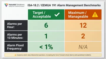
Alarm management standards (ISA-18.2 / EEMUA 191):
| Metric | Target (Acceptable) | Maximum (Manageable) |
|---|---|---|
| Alarms per hour (average) | 6 | 12 |
| Alarms per 10 minutes | 1 | 2 |
| Alarm floods | < 1% of periods with > 10 alarms | N/A |
An alarm system that triggers too many false positives trains operators to ignore it — which defeats the purpose entirely. Set dead-bands and acknowledgment requirements carefully, then test alarm behavior under simulated fault conditions before commissioning to confirm the system responds as intended.
Step 5 — Simulate and Upload the Project
Use the software's built-in simulation tool to test screen navigation, tag reads, and alarm triggers offline before uploading to the panel. This catches configuration errors before hardware testing.
Once simulation is validated, upload the project to the HMI via USB or Ethernet, then bring the PLC online and verify that live data is flowing correctly to all screen elements before declaring the programming complete.
Post-Installation Checks and Validation
IEC 62381:2024 governs Factory Acceptance Tests (FAT) and Site Acceptance Tests (SAT) for automation systems. FAT verifies design compliance at the manufacturer's facility; SAT validates real-world operational performance after installation. Both matter — skipping either creates risk that surfaces weeks into production.
Visual Inspection Checklist
Before powering up, confirm:
- All wiring terminations are secure with no loose connections
- Gasket seal is fully compressed evenly around the panel cutout
- Display is readable under the facility's ambient lighting (adjust brightness as needed)
- No physical damage to touch surface or enclosure
Functional Communications Test
With the PLC in run mode, confirm all HMI tags are receiving live data. Cycle the PLC through these key states:
- Motor start/stop
- Fault trigger
- Analog value changes
Verify the HMI displays correct status changes in real time. Static or frozen data points to a communication issue — not a programming one.
These tests catch problems that passive review misses. A missed grounding fault, an incorrect tag address, or an unchecked alarm configuration can survive initial startup and then cause a hard-to-trace fault weeks into production. A Siemens case study found that proper virtual commissioning and FAT procedures reduced commissioning time by three weeks and cut rework costs substantially.
Documentation and Handoff
Save the final HMI project file, PLC program, tag address list, and a screenshot library of all screens to a controlled location. Facilities without this documentation face longer, costlier downtime when an HMI unit needs replacement or troubleshooting months down the line.
Common HMI Setup and Programming Problems and Fixes
Most HMI problems surface during commissioning or shortly after initial startup. Left unresolved, they cause production delays and make fault-finding harder down the line. The subsections below cover the three failure types integrators and plant engineers encounter most often.
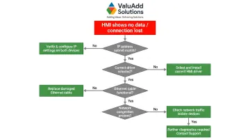
HMI Not Communicating with PLC
Problem: The HMI powers on and displays the project, but all tag values show zero, dashes, or a "connection lost" indicator.
Likely causes:
- IP address mismatch (HMI and PLC must be on the same subnet)
- Wrong communication driver selected during project configuration
- Faulty or unshielded Ethernet cable causing packet loss
- Network overload from other devices
Fix:
- Verify IP addresses on both devices match the intended subnet
- Confirm the correct driver is selected in the HMI project settings
- Swap the Ethernet cable as a first diagnostic step
- Use the HMI software's diagnostic tools to ping the PLC from within the project
- Check for loose or damaged network cabling, especially near high-power motor leads
Display Shows Corrupted or Flickering Image
Problem: The HMI screen displays garbled graphics, flickering, or areas of the screen that are unresponsive to touch.
Likely causes:
- Inadequate power supply (voltage drop under load below the panel's minimum operating voltage)
- EMI interference from nearby VFDs or motor starters coupling into unshielded power or signal wiring
- External power supply inrush currents disrupting HMI startup
Fix:
- Measure supply voltage at the HMI power terminals under load—if below the manufacturer's minimum rating, upsize the power supply or shorten cable runs
- Add ferrite cores to power and signal cables running near sources of high EMI
- Verify power supply can handle inrush currents (up to 2A depending on the model)
Tags Displaying Incorrect or Conflicting Values
Problem: A displayed value on the HMI does not match the actual process value, or a "write" action from the HMI does not produce the expected result in the PLC.
Tag errors typically trace back to one of three root causes:
- Tag is mapped to the wrong PLC memory address
- Read/write conflict exists where both the HMI and a PLC coil are writing to the same bit simultaneously
- Data scaling error on analog values
Fix:
- Cross-reference each tag address in the HMI tag database against the PLC's I/O address table
- Set PLC input data points to read-only in the HMI to eliminate write conflicts
- Re-check data scaling if analog values appear offset (verify raw value vs. scaled value)
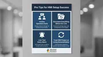
Pro Tips for Setting Up and Programming Your HMI Effectively
Even a well-planned HMI setup can fall short without the right execution habits. These four practices consistently separate clean commissioning from costly rework:
Involve operators before programming begins. Screen layouts reviewed by the people who use the HMI daily result in far fewer revision cycles. A 30-minute walkthrough before programming starts saves hours of rework after commissioning.
Document everything before going live. Save the final HMI project file, PLC program, tag address list, and screenshot library to a controlled location. When sourcing replacement panels down the line, verify that new hardware carries the same UL Listed and CE Certified ratings as the original installation to maintain compliance continuity.
Live-test every alarm. Manually trigger each defined alarm in the PLC program and confirm the correct message appears, escalates, and clears as configured. Screen design alone tells you nothing — alarm logic must be tested under live conditions to be trusted.
Treat the HMI project as living documentation. As processes evolve, screens and tag configurations should be updated, tested, and re-validated rather than patched informally. Undocumented workarounds compound quickly and make future diagnostics significantly harder.
Conclusion
A correctly set up and programmed HMI significantly improves operator visibility, reduces response time to faults, and directly supports safer, more efficient plant operations. That outcome depends entirely on executing both the physical installation and the programming with care, following manufacturer specifications and industry standards.
The most common causes of commissioning rework are avoidable with proper preparation:
- Poor upfront planning and undefined scope
- Design errors in screen logic or alarm mapping
- Inadequate communication configuration between HMI and PLC
- Missing or incomplete documentation at handoff
Facilities that follow structured FAT/SAT procedures and keep documentation current experience shorter troubleshooting windows and faster recovery when hardware needs replacement. The time invested in validation before go-live pays back every time an operator catches a fault before it becomes an unplanned shutdown.
Frequently Asked Questions
Frequently Asked Questions
How is an HMI programmed?
HMI programming means configuring communication settings, building a tag database mapped to PLC memory addresses, and designing operator screens using vendor-supplied drag-and-drop tools. It is configuration and screen development work, not traditional code writing.
What software is used for HMI?
Common platforms include FactoryTalk View Studio for Allen-Bradley/Rockwell systems, TIA Portal for Siemens, EasyBuilder Pro for Weintek units, and AutomationDirect's C-more Suite. Software is typically vendor-specific and must match the HMI hardware brand.
What programming languages are used for HMI?
Most HMI development uses graphical configuration tools rather than traditional programming languages, with scripting options such as VBScript or structured text available for advanced logic. The PLC logic driving HMI data is typically written in ladder logic or structured text.
How do you design a good HMI?
Keep screens simple and uncluttered, use consistent color coding (green/red/yellow conventions), display units of measurement on all numeric values, and limit screen navigation depth to 2-3 clicks. Always design with the operator's real-time workflow in mind rather than the engineer's perspective.
What are the 4 stages of HMI?
The four stages are requirements definition, design, development, and testing/validation. Each phase moves from clarifying what operators need to see and control, through screen layout and tag configuration, to simulation and live commissioning checks before production use.
Does an HMI need a PLC to function?
A PLC is not strictly required—HMIs can connect to a DCS, PAC, or data acquisition system via Modbus TCP. That said, PLCs and HMIs are almost universally paired in industrial automation, with the PLC handling control logic and the HMI providing the operator interface.