Introduction
A single grounding mistake in a busbar installation can mean the difference between a tripped breaker and an arc flash. Despite their mechanical simplicity, busbar systems carry one of the highest fault-current risks of any distribution component — and NEC Article 250 sets specific requirements that determine whether your system will clear that fault safely or not.
Busbar systems deliver current from service entrances to branch circuits, motor control centers, and downstream loads across industrial control panels, manufacturing facilities, and utility installations. A properly grounded busbar provides the low-impedance fault path required to trip overcurrent devices during a ground fault, protecting personnel from shock and preventing equipment damage or fire.
This guide covers:
- What NEC Article 250 requires for busbar grounding
- The step-by-step process for compliant installation
- Key variables that affect both code compliance and fault-clearing performance
- Common mistakes that cause failed inspections or unsafe fault conditions
Key Takeaways
- Grounding is mandatory under NEC Article 250, with distinct rules for service entrance panels versus subpanels
- Ground bus bars bond directly to metal enclosures; neutral and ground must remain isolated in subpanels
- GEC sizing follows NEC 250.66 (based on service conductors), while EGC sizing follows NEC 250.122 (based on breaker rating)
- Service entrance bonding requires listed bonding jumpers or bushings per NEC 250.92(B), not standard locknuts
NEC Grounding Requirements for Busbar Systems
Governing Code and Scope
NEC Article 250 is the governing code for all grounding and bonding in the United States. It applies to any electrical system that includes a busbar—from residential panels to industrial switchgear, motor control centers, and utility distribution equipment. Compliance is not optional; it's enforced by the Authority Having Jurisdiction (AHJ) at every permitted installation.
Service Entrance Bonding: NEC 250.24
At the main service panel, NEC 250.24(A)(1) requires the grounding electrode conductor (GEC) to connect to the grounded (neutral) conductor at any accessible point from the load end of the service drop to the service disconnecting means. This is the only location where neutral and ground are intentionally connected.
Critical prohibition: NEC 250.24(A)(5) strictly prohibits reconnecting the neutral to ground on the load side of the service disconnect. This rule prevents neutral current from flowing on equipment grounding conductors and metal enclosures under normal operation—a shock hazard and code violation that triggers GFCI nuisance tripping in downstream circuits.
Grounding Electrodes: NEC 250.50 and 250.52
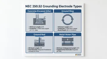
Every electrical system must connect to a grounding electrode. NEC 250.52 recognizes several electrode types:
- Concrete-Encased (Ufer): ≥20 ft of bare copper (≥4 AWG) or conductive rebar (≥½ in. diameter) encased in ≥2 in. of concrete in direct earth contact
- Ground Ring: ≥20 ft of bare copper (≥2 AWG) encircling the building, buried at least 30 inches deep
- Ground Rod: ≥8 ft in length in contact with earth; must be supplemented by a second rod spaced ≥6 ft apart unless a single rod measures ≤25 ohms resistance to earth
- Metal Underground Water Pipe: ≥10 ft in direct earth contact; must be supplemented by an additional electrode
Standardizing on concrete-encased electrodes for new construction or dual ground rods for retrofits avoids specialized resistance testing.
GEC Sizing: NEC 250.66
The grounding electrode conductor must be sized according to NEC Table 250.66, based on the size of the largest ungrounded service conductor—not the breaker size. Undersizing the GEC is one of the most common code violations.
Example for 200A service:
| Service Conductor Size | Required GEC (Copper) | Required GEC (Aluminum) |
|---|---|---|
| 2/0 AWG Cu or 4/0 AWG Al | 4 AWG Cu | 2 AWG Al |
Exception: A GEC connected solely to a ground rod need never be larger than 6 AWG copper.
Bonding Methods: NEC 250.92(B)
NEC 250.92(B) defines the acceptable methods for bonding service equipment. Standard locknuts alone do not satisfy NEC bonding requirements at service entrances, especially across concentric or eccentric knockouts. Permitted methods include:
- Listed bonding jumpers
- Grounding-type locknuts
- Bonding bushings with listed jumpers
This requirement prevents the high-resistance connections that can delay or prevent overcurrent device operation during faults.
EGC Identification and Sizing
NEC 250.119 requires wire-type equipment grounding conductors (EGCs) to be bare, green, or green with one or more yellow stripes if 6 AWG or smaller. Conductors 4 AWG and larger may be re-identified at all accessible points.
NEC 250.122 governs EGC sizing based on the rating of the overcurrent device protecting the circuit, not the service conductor size. For a 200A breaker, the minimum copper EGC is 6 AWG—a common undersizing mistake in busbar panel builds.
Both requirements apply directly to busbars: the identification rule governs how EGC taps are marked at each bus connection, while the sizing rule determines the conductor run back to the panel's ground bar.
Step-by-Step: How to Ground a Busbar System
Before touching a single conductor, confirm whether you're working on a main service panel (bonded neutral/ground) or a subpanel (isolated neutral). That single distinction drives every decision in the steps below — and mixing them up is the most common NEC compliance failure inspectors catch.
Step 1: Shut Down Power and Confirm System Type
Verify de-energization:
- Confirm the service is de-energized at the utility disconnect
- Use a non-contact voltage tester on all conductors before handling any busbar components
- Wear appropriate PPE, including arc flash-rated gloves and face shield for the voltage and available fault current
Identify panel type:
- Main service panel: Neutral and ground share a common bonding point; the main bonding jumper (MBJ) connects both to the enclosure
- Subpanel: Neutral bar must be isolated from the enclosure using insulating standoffs; ground bus bar bonds directly to the metal enclosure
Step 2: Install and Bond the Ground Bus Bar
Mount the ground bus bar:
- Secure the bar to the metal enclosure using manufacturer-supplied hardware
- The bar must make direct, low-resistance metal-to-metal contact with the panel enclosure—never use insulating standoffs for the ground bus bar
- Torque mounting screws to the manufacturer's specified value per NEC 110.14(D)
Install the main bonding jumper (main panels only):
- Connect the neutral bar and ground bus bar to the enclosure using the MBJ or factory-supplied bond strap
- Size per NEC 250.28 and Table 250.102(C)(1), based on the largest ungrounded service conductor
- Manufacturer-provided MBJs in listed equipment satisfy this requirement
For industrial control panels and motor control centers, ValuAdd's UL-listed busbar systems include factory-integrated bonding provisions that satisfy both NEC 250.28 and UL 508A requirements — reducing field modification and inspection risk.
Step 3: Connect the GEC and EGCs
Route the grounding electrode conductor:
- Run the GEC from the ground bus bar to the grounding electrode system as directly as practicable
- If routing through ferrous metal conduit, bond both ends per NEC 250.64(E) — unbonded ferrous conduit creates an inductive choke that degrades fault current return
- Size per NEC 250.66 table
Terminate equipment grounding conductors:
- Connect each EGC (bare, green, or green with yellow stripe) to a dedicated terminal on the ground bus bar
- Do not double-lug two conductors in a single terminal unless the terminal is listed for multiple conductors
- Torque all connections to the manufacturer's specification using a calibrated torque driver
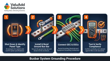
Step 4: Test and Verify Compliance
Continuity testing:
- Use a low-resistance ohmmeter or dedicated ground bond tester to verify continuity from each EGC termination point through the bus bar to the grounding electrode
- While the NEC does not specify a universal ohmic threshold for installed systems, the 25-ohm rule applies strictly to individual ground rod resistance to earth
Once electrical continuity is confirmed, shift to a documented visual review before closing the enclosure.
Visual inspection checklist:
- Correct neutral/ground separation in subpanels
- Wire identification colors match NEC 250.119
- No mechanical stress on conductors at terminations
- All connections torqued and documented for AHJ inspection
What You Need Before Grounding a Busbar System
Preparation directly affects both safety and whether the installation passes inspection. A missing component or sizing error can force a complete rework — gather everything below before starting.
Equipment and Materials
- Copper ground bus bar sized for the number of EGC terminations required
- GEC conductor sized per NEC 250.66
- Main bonding jumper or bond strap (for main panels)
- Listed grounding electrode connectors (UL 467)
- Torque wrench or calibrated screwdriver
- Tinned copper or corrosion-resistant bus bars for harsh environments (moisture, vibration, chemical exposure) — confirm UL 467 listing for grounding and bonding equipment
Tools and Safety Gear
- Non-contact voltage tester
- Low-resistance ohmmeter or ground bond tester
- Torque driver with verified calibration
- Wire stripper
- Insulated hand tools
- Arc flash-rated gloves and face shield appropriate to system voltage and available fault current
Compliance Readiness
- Obtain a copy of the NEC edition adopted in your local jurisdiction (state-level adoption varies between 2020 and 2023 editions)
- Confirm whether a permit and AHJ inspection is required before energizing
- Verify that all components are from listed manufacturers and that labeling meets NEC 110.21
Key Variables That Affect Grounding Performance
Even a correctly installed busbar can fail to perform safely if these variables are not controlled.
GEC and EGC Conductor Sizing
An undersized GEC cannot carry the full fault current during a ground fault event. It may fail before the overcurrent device operates, creating a fire or shock hazard.
NEC 250.66 ties GEC size to the service entrance conductor—not the breaker. For a 200A service with 2/0 AWG copper service conductors, the minimum GEC is 4 AWG copper. Using 6 AWG because "it's connected to a ground rod" violates the table unless the GEC connects solely to a rod electrode.
Main Panel vs. Subpanel Configuration
If a subpanel's neutral and ground share a bus bar without isolation, load current flows on equipment grounding conductors and the panel enclosure under normal operation—both a code violation and a shock hazard.
When neutral-ground bonding exists downstream of the main disconnect, GFCIs and ground fault protection devices can nuisance-trip or fail to operate entirely. The root cause: during a ground fault, current divides between the neutral and EGC, causing the GFCI current transformer to register an imbalance even under normal load conditions.
Busbar Material and Connection Resistance
Material choice directly affects how much fault current the busbar can carry. Copper and aluminum differ significantly in resistivity:
| Material | Resistivity at 20°C | Relative to Copper |
|---|---|---|
| Copper | 1.72 × 10⁻⁸ Ω·m | Baseline |
| Aluminum | 2.82 × 10⁻⁸ Ω·m | ~1.6× higher |
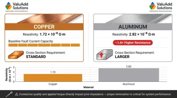
Aluminum busbars require a larger cross-section to match copper's fault current capacity. Beyond material, connection quality matters just as much. High resistance at the joint—from loose torque, corrosion, or incompatible metals—raises the impedance of the fault current path. That added impedance can slow or prevent overcurrent device operation, leaving dangerous voltages on exposed metal surfaces longer than safe.
Common Mistakes When Grounding a Busbar System
- Bonding neutral and ground in a subpanel: This is the most frequent NEC violation during panel upgrades. Neutral current flows on ground conductors and the enclosure, triggering nuisance GFCI trips and creating shock hazard on metal surfaces
- Undersizing the GEC based on breaker size: NEC 250.66 is based on service conductor size, not the overcurrent device rating
- Double-lugging multiple EGCs in terminals not rated for it: This causes loose connections over time and is a common AHJ rejection during inspection
- Skipping post-installation continuity testing: Without a ground bond test, missed connections or improper torque create high-resistance paths that only reveal themselves during a fault
When these mistakes occur, the symptoms are usually consistent. Here's how to diagnose the three most common grounding failures in the field.
Troubleshooting Common Grounding Issues
Problem: GFCI or ground fault relay trips unexpectedly under normal load
Neutral and ground are likely bonded in a subpanel downstream of the main disconnect. Verify all subpanel neutral bars are isolated from the enclosure, then use a clamp meter to measure EGC current under load — it should read near zero.
Problem: High resistance reading between ground bus bar and grounding electrode
The most common causes are a corroded or loose GEC termination, a damaged electrode, or inadequate soil contact at the ground rod. Inspect all GEC terminations with a low-resistance tester and confirm the electrode meets NEC 250.53 installation depth requirements.
Problem: Ground bus bar overheating
The bus bar cross-section may be undersized for the available fault current, or multiple conductors sharing a single terminal are creating localized resistance. Verify the bus bar ampacity rating against available fault current, inspect for discolored terminations, and re-torque all connections.
Frequently Asked Questions
Does a bus bar need to be grounded?
Yes. Under NEC Article 250, any busbar system that is part of an electrical installation must be connected to the grounding electrode system. Ungrounded busbars create an uncontrolled fault path that endangers personnel and equipment.
Can neutrals and grounds go on the same bus bar?
In the main service panel, neutral and ground are bonded at a single point per NEC 250.24. In subpanels, they must be kept on separate, isolated bars—combining them downstream of the main disconnect is a code violation.
What is NEC Code 250.92(B)?
NEC 250.92(B) defines acceptable methods for bonding service equipment, including listed bonding jumpers, bonding-type locknuts, and bonding bushings. Standard locknuts alone do not satisfy this requirement, especially across concentric or eccentric knockouts.
What are the NEC requirements for grounding a busbar?
Key requirements include:
- Connect to a qualifying grounding electrode per NEC 250.50/250.52
- Size the GEC per Table 250.66
- Size EGCs per Table 250.122
- Bond the enclosure at the service entrance per NEC 250.24
- Use identified conductors per NEC 250.119
What is the 83% rule for electrical services?
The "83% rule" is trade shorthand referencing NEC 310.12, which permits certain service conductors to be sized at 83% of the service rating—but this applies to conductors, not GECs. GECs must be sized strictly per Table 250.66 without interpolation.
Do I need a positive and negative bus bar?
Positive and negative bus bars apply to DC systems (solar, battery storage, DC control panels). In AC systems, the relevant bars are hot bus, neutral bar, and ground bus bar—all three serve distinct functions and must not be interchanged.