According to ESFI data covering 2011–2024, electrical contact accounts for over 2,000 occupational fatalities in that period. While no single statistic isolates neutral bus bar wiring errors specifically, improper bonding and termination work are well-documented contributors to energized enclosures and unexpected fault paths.
This guide is written for licensed electricians, plant engineers, and system integrators working on main service panels, subpanels, and industrial control panels. It covers the complete installation sequence — from site preparation through post-installation validation — with reference to NEC Article 250 and alignment with NFPA 70E and OSHA 29 CFR 1910.147 lockout/tagout requirements.
Key Takeaways
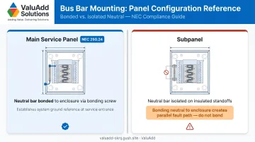
- Neutral bus bars must be mounted on insulated standoffs in subpanels — bonding to the enclosure is only correct at the main service panel
- Leaving the bonding screw installed in a subpanel is one of the most common and dangerous installation errors
- One conductor per terminal unless the terminal is explicitly listed and marked for multiple wires
- Every termination must be torqued to the manufacturer's specified value from the equipment label or product data sheet
- Do not energize until insulation checks, continuity verification, and torque confirmation are complete
Installation Guide for Neutral Bus Bars
Installation follows a defined sequence:
- Site assessment and compatibility check
- Mechanical mounting
- Conductor termination
- Bonding verification
- Validation testing
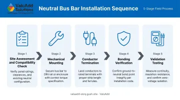
Skipping steps (particularly the bonding decision) is the most common reason installations get redone after inspection.
A careful installation in a standard subpanel typically takes one to three hours. Industrial distribution boards with high conductor counts take longer and benefit from a second person managing conductor routing. Work through the prerequisites below before picking up a tool.
Prerequisites and Safety Considerations
Before touching anything:
- De-energize the panel and apply lockout/tagout per OSHA 29 CFR 1910.147
- Verify with a calibrated non-contact voltage tester — not by assumption
- Confirm whether this is a main service panel (bonding required) or a subpanel (insulation from enclosure required); this single determination drives the entire mounting configuration
System readiness checks:
- Confirm the bus bar's current rating meets or exceeds the panel's total neutral load capacity
- Verify UL listing — products meeting UL 486A/B requirements confirm conductor material compatibility and termination ratings
- Check whether the bar is rated for copper, aluminum, or both — this must match the conductors being terminated
- If any of these points are unclear, stop and resolve them before proceeding
Tools and Parts Required
Essential tools:
- Calibrated torque screwdriver or torque wrench
- Non-contact voltage tester
- Multimeter
- Insulated screwdrivers
- Wire stripper
- Crimping tool (if using ferrules for fine-stranded wire)
- Permanent marker for conductor labeling
Components:
- Neutral bus bar — correctly rated and UL Listed for the application
- Insulated standoff kit (subpanel installations only)
- Mounting screws rated for the enclosure material
- Bonding screw — for main service panel installations only
Many panels ship with the bonding screw pre-installed. In a subpanel, remove it before mounting the bar, store it separately, and record its removal in the maintenance log. This step is easy to overlook and will fail inspection if missed.
How to Install a Neutral Bus Bar (Step-by-Step)
Step 1 — Prepare the Panel
Confirm power is off and LOTO is applied. Verify with the voltage tester on all conductors — incoming line, bus, and any feed-through conductors. Remove any conductors that will land on the neutral bar. Inspect the mounting location for burrs, debris, or corrosion that could compromise insulation integrity or mechanical contact.
Step 2 — Mount the Neutral Bus Bar
For subpanels:
- Install insulated standoff hardware at the mounting location
- Secure the neutral bar through the standoffs
- Confirm with a multimeter that zero continuity exists between the bar and the metal enclosure before proceeding — this test must pass before any conductor lands
For main service panels:
- Mount per manufacturer instructions
- Insert the bonding screw to connect the bar to the enclosure (per NEC 250.24)
The distinction between these two configurations is the foundation of NEC Article 250. Bonding the neutral to the enclosure in a subpanel creates a parallel current path through the enclosure and conduit system — a shock hazard that can also cause nuisance GFCI trips and erratic protective device behavior.
Step 3 — Prepare and Route Conductors
- Strip each neutral conductor to the manufacturer's specified strip length (marked on the bar or in the data sheet)
- Do not nick conductors — nicked strands under a set screw create high-resistance hotspots
- Route conductors to avoid crossing uninsulated hot conductors
- Pair each neutral with its corresponding circuit before terminating — this makes labeling accurate and speeds up future troubleshooting
Step 4 — Terminate Conductors
- Insert one conductor per terminal unless the terminal is explicitly marked for two conductors
- Tighten each set screw or terminal screw to the manufacturer's specified torque value — find this on the equipment torque label or in the product data sheet
On torque values: There is no universal table for neutral bus bar terminations — always confirm the exact value for your specific product. Manufacturer sources vary:
- Schneider Electric NF panelboards: torque label on the back of the deadfront
- Eaton Pow-R-Line: value shown on the switchboard label
Typical branch circuit neutral terminations run 20–50 in-lbs, but treat that range as context only, not a substitute for the product-specific value.
For fine-stranded wire, use the required ferrule before inserting the conductor. Without a ferrule, wire strands spread under the set screw and the effective contact area drops significantly over thermal cycling.
Step 5 — Label and Document
- Label each terminal with the circuit number it serves
- Photograph the completed termination before closing the panel
- Record installation date, installer name, and the torque tool used in the panel's maintenance log
In industrial environments — manufacturing, water treatment, processing plants — panel documentation is expected, and its absence raises flags during commissioning audits.
Post-Installation Checks and Validation
Do not energize until both pre-energization stages below are complete.
Visual Check
- All conductors fully seated — no insulation inside the terminal barrel, no exposed bare conductor outside it
- No stray strands touching adjacent terminals
- Bar mechanically secure with no movement on standoffs
Electrical Verification (Panel De-Energized)
- Continuity confirmed: Neutral bar to neutral feeder conductor
- Zero continuity confirmed: Neutral bar to panel enclosure (subpanel only)
- Bonding screw present and secure: Main service panel only
These checks align with the acceptance testing framework established in ANSI/NETA ATS-2025, which covers suitability for initial energization and installation to design specifications.
After Energizing
- Check for voltage between the neutral bar and the enclosure. In a subpanel, any reading above 1–2 mV indicates an unwanted bonding path that must be investigated before continued operation.
- After 15–30 minutes under load, check terminations for abnormal heat using a thermal camera or contact probe. A hot terminal at this stage points to an undertorqued or improperly seated connection.
Common Installation Problems and Fixes
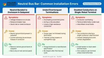
Neutral Bar Bonded to Enclosure in a Subpanel
Symptoms include energized equipment frames, unexplained GFCI trips, and measurable voltage between the enclosure and true earth ground. The bonding screw was left installed, bridging hardware crossed the insulated standoffs, or a ground bar was used where a neutral bar was required.
To fix:
- De-energize and apply LOTO
- Remove the bonding screw or any bridging hardware
- Verify zero continuity between the neutral bar and enclosure before re-energizing
Governed by NEC 250.24(A)(5) and 250.142(B).
Undertorqued or Overtorqued Terminations
Symptoms include terminals running hot under load, conductors that feel loose when pulled, and arcing marks on the bar or insulation. Common causes: connections tightened by feel, wrong torque value referenced, or ferrules omitted on fine-stranded wire — allowing strands to spread under the screw.
To fix:
- De-energize the panel
- Retorque all connections to manufacturer spec using a calibrated torque screwdriver
- Install ferrules on fine-stranded conductors before re-terminating
- Replace any bar or conductor with visible arcing or heat damage
Doubling Conductors on a Single-Rated Terminal
Symptoms include a lighter-gauge wire seating poorly in a shared terminal, overheating under load, and voltage imbalance on the affected circuit. This happens when installers run short on terminal positions and double up conductors, or assume a terminal is dual-rated when it isn't.
To fix:
- Replace the neutral bar with one that has sufficient terminal positions, or add a supplementary bar
- Only use dual-conductor terminations where the terminal is explicitly listed and marked for that configuration
NEC 408.41 governs grounded conductor terminal rules for panelboards.
Pro Tips for Installing Neutral Bus Bars Effectively
Select a bar with at least 20% more terminal positions than your current circuit count. Replacing a bar after all conductors are dressed and terminated is a significant rework event.
Confirm the bar's UL listing covers aluminum terminations if the panel may ever use aluminum branch circuit wiring. A copper-only rated bar will require full replacement the moment aluminum conductors are introduced.
Record the bonding configuration and termination torque values in the panel maintenance log at installation — not after. This directly reduces troubleshooting burden during future faults and speeds inspection approvals. The ANSI/NETA MTS-2023 framework provides the maintenance testing standard this documentation supports.
Physically inspect and test with a multimeter before accepting any relocated panel. A subpanel moved from another location may still have its bonding screw installed — a fault waiting to surface.
Bring in a licensed electrician when anything is unclear. Neutral bus bar wiring errors often pass initial visual inspection and only reveal themselves under fault conditions or during arc flash events.
If you're specifying bus bar solutions for industrial control panels or distribution boards, ValuAdd's technical team can work through configuration requirements with you — including terminal count, conductor compatibility, and enclosure fit for your specific load profile.
Frequently Asked Questions
Can I put a neutral and ground on the same bus bar?
Only at the main service panel or first means of disconnect, where the main bonding jumper intentionally connects them. In all subpanels and downstream distribution points, neutral and ground must terminate on separate, isolated bars — sharing one bar creates dangerous parallel current paths through the grounding system.
Can I touch the neutral bus bar?
Not while the panel is energized. The neutral bar carries live return current during normal operation. Always de-energize, apply lockout/tagout per OSHA 1910.147, and verify with a voltage tester before making contact with the bar or any terminated conductors.
What is a neutral bus bar?
A neutral bus bar is a metal bar (typically tin-plated aluminum or brass) mounted inside an electrical panel that provides a common termination point for all neutral conductors from branch circuits. Unlike a ground bar, it carries return current continuously under normal operating conditions.
What is the difference between a neutral bar and a ground bar?
A neutral bar carries return current during normal operation and must be insulated from the enclosure in subpanels. A ground bar carries fault current only, mounts to and bonds with the enclosure. Swapping them or incorrectly connecting them is both a code violation and a direct safety hazard.
Does the neutral bus bar need to be insulated from the panel enclosure?
Yes. In any subpanel or downstream distribution panel, the neutral bar must mount on insulated standoffs with no electrical contact with the metal enclosure. Only in the main service panel is the neutral bar intentionally bonded to the enclosure via the main bonding jumper, as required by NEC 250.24.
How many wires can I connect to one neutral bus bar terminal?
One conductor per terminal, unless the terminal is specifically listed and marked for multiple conductors. Doubling up creates uneven contact pressure, overheating risk, and a NEC 408.41 violation. Check the bar's UL listing and manufacturer documentation before terminating more than one wire per hole.