
Only qualified electricians or plant engineers familiar with three-phase motor control systems should perform this installation. In-house maintenance teams should proceed only if they have experience with motor control panels and relevant NEC or local code compliance knowledge. Attempting this work without proper training increases the risk of equipment failure and safety hazards.
Several problems arise from incorrect wiring: phase reversal can damage the motor, missing control circuit connections trigger fault protection unnecessarily, improper grounding causes persistent ground faults, and skipping a bypass contactor on continuously running motors leads to SCR overheating and premature failure.
This guide covers the full soft starter wiring process—from selecting the right wiring method and meeting safety prerequisites, to executing step-by-step power and control circuit connections, and completing post-installation validation.
Key Takeaways
- Soft starter installation requires both main power circuit and control circuit wiring—missing either causes faults
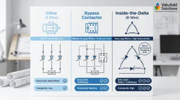
- Three wiring methods exist: inline (3-wire), bypass contactor, and inside-the-delta (6-wire); choose based on motor size and duty cycle
- Always isolate and lock out power before starting; verify motor FLA matches soft starter ratings
- Wire control circuit terminals correctly; wrong connections disable fault protection or leave the motor exposed
- Validate installation with a no-load test before connecting to full system load
Soft Starter Wiring Guide
The wiring process consists of four phases: pre-installation checks, wiring method selection, main circuit and control circuit connections, and initial commissioning. Shortcutting any phase commonly causes installation failures in field settings.
A standard inline installation takes 2–4 hours for a qualified technician. Inside-the-delta wiring may require an additional hour and higher electrical familiarity. All three-phase work requires proper PPE and LOTO compliance.
Prerequisites and Safety Considerations
Verify these requirements before wiring begins:
- Confirm the soft starter's rated current (FLA) matches or exceeds the motor's nameplate FLA
- Verify voltage rating alignment (208V, 480V, 600V, or medium voltage)
- Check enclosure IP/NEMA rating for the installation environment
Site readiness requires:
- Adequate enclosure space for heat dissipation with minimum clearance above and below for airflow
- DIN rail or panel mounting availability
- Proximity to motor and power source
Before touching any terminals:
- Power must be fully de-energized and locked out (LOTO procedure) before any wiring begins
- Never work on a soft starter with live voltage present
- Confirm with a meter that all phases read zero before touching terminals
- Do not proceed if the soft starter has no visible input/output terminal labeling — consult the manufacturer's wiring diagram
According to OSHA 29 CFR 1910.147 and NFPA 70E-2024, an Electrically Safe Work Condition (ESWC) must be established before servicing equipment operating at 50 volts or greater.
Tools and Parts Required
Essential components for a complete installation:
- Soft starter unit (appropriately rated)
- Disconnect switch or circuit breaker sized per NEC Article 430.52 for motor FLA
- Main power cable sized for full load current
- Control wiring (typically 16–18 AWG shielded)
- Bypass contactor (if not internally integrated)
- Semiconductor fuses (strongly recommended for thyristor protection)
- Grounding conductor
Recommended additions:
- Line-side isolation contactor
- DIN rail terminal blocks for neat control circuit termination
- Cable ferrules for reliable terminal block connections
Semiconductor fuses are distinct from standard motor branch circuit fuses and should not be substituted. IEC 60269 defines aR-class fuses as required for SCR protection, achieving Type 2 (no damage to starter or motor on short-circuit) coordination.
Choosing the Right Wiring Method
Three standard methods exist, each suited to different applications.
Inline (3-Wire)
The soft starter wires directly in series between the power supply and motor — all motor current passes through the SCRs. Best for motors up to approximately 20 HP (15 kW), intermittent-duty cycles, or panel installations with space constraints.
Bypass Contactor (Inline + External Bypass)
An isolation contactor wires in parallel with the soft starter output. After the motor reaches full speed, the bypass contactor closes and routes current around the SCRs, reducing heat dissipation and extending soft starter life. This is the standard approach for larger motors and continuous-duty applications.
Inside-the-Delta (6-Wire)
The soft starter connects inside the delta winding of a 3-phase motor, handling only approximately 58% of line current (1/√3). This lets you specify a smaller, lower-rated starter for high-horsepower motors — at the cost of added complexity and requiring access to all six motor winding terminals.
Quick selection reference:
| Application | Recommended Method |
|---|---|
| Small motors (≤20 HP) or intermittent duty | Inline (3-wire) |
| Medium-to-large motors in continuous operation | Bypass contactor |
| Very large motors where starter cost reduction matters | Inside-the-delta (6-wire) |
For applications where an external bypass contactor would otherwise be required, ValuAdd's CSXi Series includes an integrated bypass contactor rated at 99.5% runtime efficiency — simplifying panel design without sacrificing protection.
How to Wire a Soft Starter: Step-by-Step
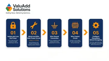
Wiring follows a defined order: power isolation, mounting, main circuit, ground, control circuit, parameter setup. Reversing that order or skipping steps is responsible for a majority of installation faults and failed first starts.
Step 1 — Isolate and Lock Out Power
Open the upstream disconnect, apply a LOTO lock, and verify with a multimeter that all three phases at the installation point read zero voltage. Do not rely on visual confirmation alone.
Step 2 — Mount the Soft Starter and Wire the Main Power Circuit
Mount the unit vertically in the enclosure with adequate airflow clearance. Connect the three-phase supply to input terminals L1, L2, L3 per IEC 60947-4-2 Annex A. Connect output terminals T1, T2, T3 to the motor.
Verify phase sequence using the motor nameplate and soft starter documentation — incorrect phase sequence on some units triggers a fault on first start.
If your application requires optional wiring configurations, follow the method that matches your topology:
- Bypass contactor: Connect the contactor in parallel across T1/T2/T3 to the motor; wire the bypass relay output (typically terminals 1 and 2) to the contactor coil
- Inside-the-delta: Access the motor terminal box and connect the soft starter across two phases of the delta winding per the manufacturer's diagram — this reduces the starter's current exposure to roughly 58% of line current
- Standard in-line: No modifications needed; L1/L2/L3 in, T1/T2/T3 out to motor as described above
Step 3 — Wire the Ground Connection
Connect the equipment ground from the panel ground bus to the soft starter ground terminal. Ground the motor separately per NEC requirements. Never rely on mounting hardware alone for grounding — a dedicated ground conductor is required.
Step 4 — Wire the Control Circuit
Wire control terminals according to your control scheme:
| Function | Terminals | Notes |
|---|---|---|
| 3-wire start/stop | 8, 9, 10 | Momentary pushbutton control |
| 2-wire control | 8 and 10 | Maintained contact (PLC or switch) |
| Fault relay output | 5/6 | Wire to upstream protection or PLC input |
| External instantaneous stop | 7 | Normally closed contact of protection device |
If no external stop device is installed, jumper terminal 7 to terminal 10. Leaving terminal 7 open holds the starter in a continuous fault state.
Use shielded cable for all control wiring, with the shield grounded at one end only — floating the shield at the device end prevents ground loops that introduce noise into control signals.
Step 5 — Configure Initial Parameters Before First Energization
Before restoring power, set the motor FLA on the soft starter's parameter menu (typically the first required setting). Set the initial voltage and acceleration time based on the motor's load characteristics.
Typical starting point:
- Pumps and fans: 30–40% initial voltage with a 10-second ramp time
- Heavier loads: May require adjustment upward
Before energizing, confirm the motor FLA setting against the nameplate, review the manufacturer's fault code list, and have the parameter sheet on hand — first-start faults are easier to diagnose when you can compare against the factory defaults immediately.
Post-Wiring Checks and First-Start Validation
Pre-Energization Checks
Before restoring power, perform a visual inspection of all terminal connections:
- Verify no conductors are touching adjacent terminals
- Confirm all terminals are tightened to the torque specification in the product datasheet
- Verify the bypass contactor (if used) is correctly oriented
- Use a continuity tester to verify the control circuit path from start button through the soft starter control terminals
- Confirm the grounding conductor is continuous from panel ground to soft starter to motor frame
First-Start Sequence
Restore power to the soft starter (not the motor) and confirm that the unit powers up without fault indicators. Initiate a no-load or lightly loaded test start:
- Observe the ramp-up behavior
- Confirm the motor accelerates smoothly
- Check that the bypass contactor closes cleanly at end of ramp (if applicable)
If a fault code appears, reference the manufacturer's fault code table before making any wiring changes — this step often resolves issues faster than re-inspecting connections.
Indicators of Correct vs. Incorrect Installation
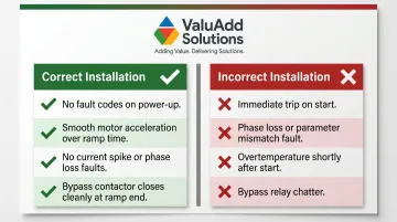
A successful first start has clear, observable markers. Use the following as a quick reference when evaluating your results:
Signs the installation is correct:
- Unit powers up without fault codes
- Motor accelerates smoothly over the programmed ramp time
- No current spike faults, phase loss faults, or bypass relay chatter
- Bypass contactor closes cleanly at end of start ramp
Signs of an installation problem:
- Immediate trip on start (indicates wiring error or parameter mismatch)
- Overtemperature shortly after start (suggests inadequate ventilation or missing bypass contactor)
Common Wiring Problems and Fixes
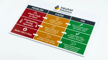
Motor Trips Immediately on Start with a Phase Fault
Problem: The soft starter shows a phase loss or phase sequence fault immediately when a start command is given.
Cause: One of the three input phases (L1/L2/L3) is not fully connected or has a loose terminal. Alternatively, the phase sequence is reversed for a unit requiring specific phase rotation.
Fix:
- Torque all three input phase terminals (L1/L2/L3) to the specified value using a torque screwdriver
- Use a phase rotation meter to confirm incoming phase sequence matches the soft starter's requirement
- If the unit is phase-sequence-sensitive, swap any two input phase conductors to reverse rotation
Soft Starter Overheats During Normal Operation
Problem: The soft starter's thermal protection trips during normal running, not during starting.
Cause: The bypass contactor is either not wired, not functioning, or the bypass relay output terminals were not connected to the contactor coil. This means the SCRs continuously conduct full load current after starting, generating excess heat.
Fix:
- Verify bypass relay output terminals (typically terminals 1 and 2) are wired to the contactor coil and that the contactor closes once the ramp completes
- Confirm enclosure ventilation meets minimum clearance specs
- For models with an internal bypass, check that it is enabled in parameter settings
Motor Runs but Fails to Stop on Stop Command
Problem: Sending a stop command from the control circuit does not stop the motor.
Cause: The stop input (terminal 9 in a 3-wire control scheme) is not correctly wired, or the start/stop inputs are configured for 2-wire instead of 3-wire control (or vice versa), causing the control logic to ignore the stop signal.
Fix:
- Pull the wiring diagram for your specific model and confirm whether the application uses 2-wire (maintained contact) or 3-wire (momentary contact) control
- Verify terminal connections match that control configuration
- With the motor running, measure continuity through the stop contact to confirm the input is reaching the soft starter
Pro Tips for Wiring a Soft Starter Effectively
Keep these practices in mind across every installation:
- Complete and verify the main power circuit before wiring the control circuit — this prevents energizing control wiring while power conductors are still open
- Record all parameter settings with the initial values configured during commissioning; this speeds up troubleshooting and future replacements
- Label all control terminals at both ends of the wire run
For installations in wet, dusty, or chemically aggressive environments — common in water treatment and oil & gas — the soft starter's enclosure rating must match the site classification. NEMA Type 4X or IP66/IP68-rated units are required for harsh locations.
ValuAdd's soft starter portfolio includes models with these certifications, with technical support available to match the right unit to your motor and application.
Inside-the-delta wiring on motors above 200 HP, or any medium-voltage installation (3 kV–10 kV), requires a licensed electrical engineer and the manufacturer's field commissioning documentation. Low-voltage wiring practices don't transfer directly: the protection scheme, isolation, and grounding requirements are fundamentally different.
ValuAdd's MVE-P Series covers medium-voltage applications from 2.3 kV to 15 kV, with modular designs and fiber-optic isolation built for these more demanding safety requirements.
Conclusion
Wiring quality directly determines soft starter performance, motor longevity, and system safety. An improperly wired unit may appear to function on first start but create thermal, mechanical, or fault conditions that surface weeks later under load.
That delayed failure risk is why the steps before energization matter as much as the wiring itself. Before signing off on any installation, confirm each of the following:
- All wiring verified against manufacturer diagrams and NEC requirements
- LOTO procedures completed and documented before any live testing
- First-start validation performed under no-load or reduced-load conditions
- Motor current and ramp behavior confirmed within specified parameters
A soft starter installed correctly the first time protects both the equipment and the people depending on it.
Frequently Asked Questions
Do you need a contactor with a soft starter?
A bypass contactor is not always required but is strongly recommended for continuous-duty applications; it routes current around the SCRs after starting to prevent overheating. Some models, like ValuAdd's CSXi Series, include an integrated bypass contactor, eliminating the need for an external one.
Is a soft-start just a capacitor?
A soft starter is not a capacitor. It uses silicon-controlled rectifiers (SCRs or thyristors) to gradually ramp up voltage to the motor. Capacitors are used for power factor correction—a separate function with no role in voltage ramp control.
Can you put a soft start kit on a 2 stage compressor?
Yes, provided the soft starter is rated for the motor's FLA and starting torque requirements. Two-stage compressors often have high starting torque demands, so verify the starter's torque capability and select a high-torque model if standard torque reduction causes stalling.
What size circuit breaker do I need for a soft starter?
The upstream circuit breaker should be sized at 150–200% of the motor's full-load amperage (FLA) per NEC Article 430.52, using an inverse-time breaker. Semiconductor fuses, sized separately per the soft starter manufacturer's specification, are also recommended in series to protect the internal thyristors.
Can I wire a soft starter to a single-phase motor?
Standard industrial soft starters are designed for three-phase motors only. Single-phase soft-start solutions exist as a separate product category with different circuitry and are not interchangeable with three-phase units.
How do I know if my soft starter is wired correctly?
Correct wiring is confirmed when the unit powers up without fault codes, the motor accelerates smoothly over the programmed ramp time, and the bypass contactor (if used) closes cleanly at ramp completion. Any immediate fault on first start — phase loss, ground fault, or overcurrent — points to a wiring error that must be diagnosed before running under load.