This work requires qualified electricians or licensed plant engineers familiar with NEC requirements, NFPA 70E lockout/tagout (LOTO) procedures, and your facility's electrical system architecture. While trained in-house maintenance teams may handle straightforward replacements on simple units, upgrades or retrofits typically require a licensed electrician to ensure all code requirements are met and safety protocols are followed.
This guide covers the full replacement process—from pre-replacement assessment and compliance verification through step-by-step installation and post-commissioning validation—with specific attention to upgrade and retrofit considerations that can impact project scope and timeline.
Key Takeaways
- De-energize fully, follow LOTO procedures, and confirm the new switch meets or exceeds the original voltage, amperage, and interrupt ratings
- Assess existing wiring, conduit fill, and breaker coordination before upgrading—this is never a simple physical swap
- Required tools: multimeter, insulated hand tools, torque wrench, and conductors rated for the circuit
- Test under load after installation to confirm proper operation before returning the circuit to service
- If resizing conductors or modifying the panel, involve a licensed electrician—this moves beyond standard replacement
Disconnect Switch Replacement: Full Guide
This replacement process covers four phases: pre-replacement assessment, safe removal of the old unit, installation of the new switch, and post-installation validation. Skipping assessment or validation is where most failures originate — and where liability exposure is highest in industrial settings.
Project timeline expectations:
- Like-for-like swap: 2–4 hours for a straightforward replacement
- Upgrade or retrofit: Full day or more if conductor resizing, enclosure relocation, or panel modifications are required
- Permit processing: Additional 1–3 business days depending on jurisdiction
Planning and Assessment Before Replacement
Identify what triggered the replacement need:
- Failed or degraded unit – Burned contacts, failed pull-out, loose lugs, or visible overheating
- Planned upgrade – Higher amperage load, more demanding environment, improved safety features
- Compliance retrofit – Updated code requirements or improved arc-flash protection
Each scenario determines your project scope and required documentation.
Document existing specifications before removal:
- Voltage rating and system type (single-phase, three-phase)
- Amperage (horsepower) rating from the nameplate
- Interrupt capacity (kA rating)
- NEMA enclosure type (Type 1, 12, 4X, etc.)
- Fused vs. non-fused configuration
- Photograph all wiring configurations, wire colors, and terminal labels
Once you've documented the existing setup, assess whether your infrastructure can support the new switch — particularly for upgrades and retrofits.
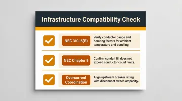
Infrastructure compatibility for upgrades or retrofits:
Upsizing the disconnect without addressing undersized conductors creates a hazardous condition and a code violation. NEC 430.22 requires conductors supplying single motors to have an ampacity of at least 125% of the motor's full-load current. Verify:
- Conductor gauge meets the new amperage rating after applying NEC 310.15(B) derating factors
- Conduit fill complies with NEC Chapter 9 for the number of conductors
- Upstream breaker or fuse rating coordinates properly with the new switch
Certification and compliance verification:
Your replacement unit must carry appropriate certifications:
- UL Listed for your specific use case and application
- Correct NEMA enclosure type – NEMA 4X for wet or corrosive industrial environments, NEMA 12 for dust-prone indoor locations
- Load-break compliance where the switch must interrupt under load (verify for motor disconnect applications)
ValuAdd's disconnect switches carry UL 98 and UL 98B certifications, with ratings up to 1500 VDC and 2000A — covering the full range of industrial motor disconnect requirements.
Permit requirements:
Many jurisdictions require permits when replacing a disconnect with a higher-rated unit or relocating the enclosure. The Authority Having Jurisdiction (AHJ) enforces these requirements under NEC 90.2. Proceeding without required permits can void equipment warranties and create significant liability. Contact your local building department before beginning work.
Safety Prerequisites and Required Tools
Non-negotiable safety requirements:
The circuit must be fully de-energized at the upstream breaker or fuse, with complete LOTO procedures per NFPA 70E applied before any work begins. After lockout, verify absence of voltage at all disconnect terminals using a calibrated multimeter or properly rated voltage tester. Never assume power is off based solely on breaker position.
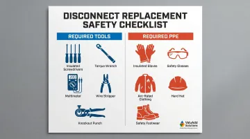
Required tools and materials:
- Insulated screwdrivers and wrenches (voltage-rated)
- Wire stripper/crimper and appropriate lugs
- Torque screwdriver or torque wrench (for terminal torque specs)
- Multimeter with appropriate CAT rating for your system voltage
- Conduit knockout punch or hole saw (if modifying enclosure)
- Anti-oxidant compound for aluminum conductors
- Replacement disconnect switch with all hardware and knockouts
- Lock-out/tag-out devices appropriate to your facility
Personal protective equipment (PPE):
- Insulated gloves rated for the voltage
- Safety glasses with side shields
- Arc-flash PPE appropriate to the incident energy level (minimum 1.2 cal/cm² exposure requires arc-rated clothing)
- Hard hat and electrical-rated safety footwear
Do not proceed if:
- The circuit cannot be fully de-energized
- Upstream protection cannot be positively locked out
- The new switch's ratings do not meet or exceed the existing unit's requirements
- Required PPE is unavailable or inadequate for the incident energy level
How to Replace a Disconnect Switch: Step-by-Step
Do not restore power at any point until verification in Step 5 is complete. Reconnecting too early is the leading cause of arc flash incidents during disconnect replacements.
Step 1 – De-energize and apply LOTO
Open the upstream breaker or fuse disconnect, apply lockout device and danger tag per your facility's LOTO procedure, and verify absence of voltage at all terminals using a properly rated multimeter. NFPA 70E requires "live-dead-live" testing: verify your meter works on a known voltage source, test all conductors at the disconnect, then verify your meter still works.
Test all conductors—line, load, and neutral/ground—before touching anything.
Step 2 – Document and remove wiring
Photograph or label every wire, noting which terminal it connects to (line vs. load side, L1/L2/L3, neutral, ground). Loosen terminal screws in sequence and carefully remove conductors. Inspect wire insulation and lug condition; note any evidence of:
- Overheating (discolored insulation, melted material)
- Corrosion at connection points
- Physical damage that requires addressing before reconnection
Step 3 – Remove the old switch and prepare the enclosure
Unscrew the disconnect from its mounting surface. If reusing the enclosure, inspect for corrosion, cracks, or gasket degradation. For new enclosures, prepare knockouts to match existing conduit entries using a proper knockout punch for clean holes. Install conduit connectors rated for the conduit type and environmental exposure (NEMA 4X requires liquid-tight fittings in wet environments).
Step 4 – Mount and wire the new switch
Secure the new enclosure or switch body to the mounting surface using hardware appropriate for the substrate. Route conductors into the enclosure through the conduit connectors. Connect:
- Line-side conductors (from power source) to line terminals
- Load-side conductors (to equipment) to load terminals
- Follow the wiring diagram supplied with the new switch
Tighten all terminal screws to manufacturer's specified torque values. NEC 110.14(D) mandates using an approved means (calibrated torque tool) to achieve specified torque. Under- or over-torquing is a leading cause of connection failure—loose connections can reach 1200–1300°C and initiate fires.
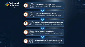
Step 5 – Verify grounding and enclosure integrity
Confirm the equipment grounding conductor is properly terminated to the grounding lug inside the enclosure. For NEMA 4X enclosures, verify that:
- All conduit entries are sealed with appropriate liquid-tight fittings
- The enclosure gasket is seated correctly without compression damage
- All unused knockouts are sealed with rated plugs
- The cover closes completely and all screws are torqued to spec
Post-Replacement Validation and Commissioning
With installation complete, move through a structured validation sequence before restoring power. Skipping any check here negates the care taken during installation.
Visual inspection before re-energization:
- All terminals are tight and torqued to specification
- No exposed conductors extend outside terminal lugs
- All knockout seals are in place
- Enclosure cover is properly seated with gasket intact
- LOTO devices remain applied until all checks complete
Electrical testing before power restoration:
Perform continuity testing to verify proper connections. Use an insulation resistance tester (megger) on circuit conductors to confirm no insulation damage occurred during replacement. Typical acceptance thresholds for low-voltage industrial circuits are minimum 1 megohm resistance to ground, though IEEE 43 standards recommend higher values for rotating machinery.
Power restoration and functional testing:
Remove LOTO devices only after all checks are complete and all personnel are clear of the equipment. Restore upstream power, then operate the disconnect switch through its full open-close cycle while observing for:
- Sparking or arcing at contacts
- Unusual resistance or binding in operation
- Abnormal sounds or vibration
- Proper indication of switch position
For load-break rated switches, confirm the switch operates smoothly under normal operating load without issue.
Documentation and record-keeping:
Record the new switch's make, model, ratings, and installation date. Update the facility's single-line diagram if conductor sizes or device ratings changed. This documentation is essential for:
- Future maintenance and troubleshooting
- Compliance audits and inspections
- Arc-flash hazard analysis updates
- Warranty claims if issues arise
Common Replacement Problems and Fixes
Most issues encountered during or immediately after replacement fall into three categories: sizing mismatches, terminal torque errors, and enclosure sealing failures.
Wiring Reconnected in Wrong Configuration
Problem: Equipment fails to start or trips immediately after restoration; voltmeter shows imbalanced or absent phase voltage at the load side.
Likely cause: Line and load terminals swapped, or a conductor connected to the wrong terminal during reinstallation—particularly common when pre-installation documentation steps were skipped.
Fix: Re-apply LOTO procedures, then re-verify all terminal connections against the switch wiring diagram and pre-removal photos.
Overheating at Terminals After Commissioning
Problem: Terminals or lugs run hot during normal operation; discoloration or burning smell observed at the enclosure within days of commissioning.
Likely cause: Terminal screws not torqued to manufacturer's specification, or mismatched conductor gauge (undersized wire for the new switch's amperage rating). Research shows that improperly torqued connections can dissipate up to 35 watts of power at the connection point.
Fix: Re-apply LOTO, re-torque all connections to spec using a calibrated torque driver, and verify conductor ampacity against NEC tables for the connected load. If conductors are undersized for the new switch's rating, replace them before returning the circuit to service.
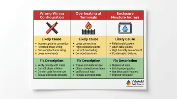
Enclosure Ingress or Moisture After Installation
Problem: Condensation, water ingress, or corrosion appears inside the enclosure in a wet or wash-down environment shortly after installation.
Likely cause: Conduit entries not sealed with NEMA 4X-rated liquid-tight fittings, or enclosure gasket not fully seated after cover installation. NEMA 4X enclosures provide protection against corrosion and water ingress when properly installed.
Fix: Remove cover, inspect and re-seat gasket, replace if damaged. Replace conduit fittings with liquid-tight connectors rated for NEMA 4X or the applicable enclosure type. Verify that all unused knockouts are sealed with appropriate rated plugs.
Catching these issues early — before the circuit returns to full load — prevents damage to conductors, connected equipment, and the switch itself.
Pro Tips for Disconnect Switch Upgrade and Retrofit Success
When upgrading to a higher-amperage or better-rated disconnect, treat the project as a partial circuit review—not just a hardware swap. Verify that:
- The upstream overcurrent protection device coordinates with the new switch's interrupt rating
- Wire gauge and conduit fill comply with the new load requirements
- Panel bus bars can handle the increased current without overheating
- Any downstream devices remain properly protected
- The surrounding infrastructure keeps pace with the upgrade—mismatches create new failure points
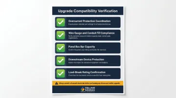
In industrial environments where the disconnect must interrupt under motor load—emergency stop scenarios, for example—confirm the replacement switch carries an appropriate load-break rating. Non-load-break switches operated under load will arc and fail prematurely, often without warning.
Always update documentation after any replacement or upgrade:
- Revise the single-line diagram to reflect new ratings
- Update the equipment tag on the enclosure with the new switch's specifications
- File the installation record in the facility's electrical maintenance log
- In facilities subject to NFPA 70E arc-flash program requirements, re-evaluate whether the arc-flash label needs updating if fault current or clearing time has changed
Conclusion
The quality of a disconnect switch replacement—from initial assessment through final commissioning—determines the long-term safety, reliability, and compliance of the circuit it protects. A properly specified, correctly installed, and thoroughly validated replacement reduces unplanned downtime and keeps personnel safe throughout the equipment's service life.
Don't treat this as a simple swap. Before closing the panel:
- Verify ratings against your actual load requirements
- Follow LOTO procedures without exception
- Torque terminals to specification using calibrated tools
- Document everything for future reference
When the scope expands beyond a like-for-like replacement—particularly when upgrading amperage ratings or modifying enclosures—involve a licensed electrician and secure appropriate permits before work begins.
Frequently Asked Questions
Frequently Asked Questions
How much does it cost to replace a disconnect?
Industrial disconnect switch replacement typically ranges from $500 to $3,000+, varying based on amperage rating (30A to 1200A), NEMA enclosure type, whether conductor upgrades are needed, and licensed electrician labor rates in your region. Higher-amperage units and specialty NEMA 4X stainless enclosures command premium pricing.
How to choose the right disconnect switch?
Three criteria drive the selection:
- Match voltage and amperage ratings to your connected load per NEC requirements
- Select the correct NEMA enclosure type (Type 12 for dust, Type 4X for wet or corrosive environments)
- Choose fused/non-fused and load-break/non-load-break configurations based on whether the switch must interrupt under load
Can you upgrade a breaker switch?
Yes, but only if existing wiring, conduit, and upstream protection all support the new rating. Upsizing the device without addressing the full circuit creates a code violation and serious safety hazard. Conductor ampacity must be verified against NEC tables before upgrading any protective device.
Can a pull-out disconnect go bad?
Yes, pull-out disconnects fail through burned or corroded contacts, degraded or melted fuse carriers, or mechanical failure of the pull-out block. Common warning signs include intermittent power loss, heat at the enclosure during operation, or visible discoloration around contact points.
Are disconnect switches wiring devices?
No, disconnect switches are classified as "disconnecting means" under the NEC, not wiring devices. They are part of the overcurrent protection and isolation system for a circuit, distinct from receptacles, switches, and similar wiring devices covered under different NEC articles.
Can I upgrade a disconnect assembly without replacing all conductors?
Often, no — if existing conductors are correctly sized for the new rating, full replacement is unnecessary. All branch circuits and feeder conductors must still be evaluated by a licensed electrician to verify compatibility before any upgrade proceeds.