Introduction
A miswired disconnect switch doesn't fail quietly — it fails with arcing, overheating, or an arc flash incident that takes equipment and personnel out of commission. Getting the installation right the first time means understanding what NEC Article 430 requires, respecting the line-side/load-side boundary, and matching the switch to the actual load.
A qualified electrician must handle all line-side (incoming) connections. Trained in-house electrical teams may perform load-side wiring and mounting where local authority permits.
The most common installation mistakes — and their consequences — include:
- Loose terminations: Cause arcing and overheating; NFPA research confirms loose connections in small enclosures can ignite nearby combustibles
- Incorrect ampere or HP ratings: Lead to nuisance tripping or catastrophic failure under load
- Enclosure mismatches: Expose internal components to moisture or contaminants, creating NEC violations
This guide walks through the full installation process — from site preparation and enclosure mounting through conductor termination and post-installation validation — following NEC and industry best-practice standards.
Key Takeaways
- De-energize upstream circuits, verify zero voltage, and follow NEC 430.102 placement rules before touching any wiring
- Select a switch rated for correct voltage, minimum 115% of motor FLA, and proper horsepower
- Match NEMA enclosure type (4X, 12, or 3R) to the environment: indoor, outdoor, washdown, or hazardous
- Torque all terminations to manufacturer specifications using calibrated tools per NEC 110.14(D)
- Test for complete circuit isolation and confirm all functions before re-energizing
Installation Guide for a Disconnect Switch
A disconnect switch installation consists of four phases: site and compliance preparation, physical mounting and conduit work, conductor termination, and functional validation. A typical single-phase or three-phase motor disconnect installation takes a qualified electrician 2–4 hours. Complex setups involving fusible switches, larger conductors, or coordination with plant shutdowns require longer timeframes and advance scheduling.
Prerequisites and Safety Considerations
Before work begins, confirm the upstream feeder or panel circuit is de-energized and locked out using a documented Lockout/Tagout (LOTO) procedure per OSHA 29 CFR 1910.147. Voltage absence must be verified with a calibrated non-contact or solenoid voltage tester. Never assume it. NFPA 70E Article 120 requires workers to test each phase conductor to verify the absence of voltage.
System Readiness Checklist:
- Mounting surface or enclosure location is within sight of the motor or driven equipment per NEC 430.102
- Space meets NEMA working clearance requirements
- Conduit routing is planned to avoid heat sources, sharp edges, or mechanical hazards
- Local Authority Having Jurisdiction (AHJ) permit requirements are confirmed
Switch Selection Criteria:
The disconnect must match system voltage and carry an ampere rating of at least 115% of the motor's full-load ampere (FLA) draw per NEC 430.110. It must also carry a horsepower rating at or above the motor nameplate HP.
NEMA Enclosure Selection:
| NEMA Type | Environment | Protection Level |
|---|---|---|
| Type 1 | Indoor | General purpose; protects against falling dirt |
| Type 12 | Indoor | Protects against dust, dirt, and dripping non-corrosive liquids |
| Type 3R | Outdoor | Rainproof and sleet-resistant |
| Type 4 | Indoor/Outdoor | Watertight, dust-tight; withstands hose-directed water |
| Type 4X | Indoor/Outdoor | Same as Type 4, plus corrosion resistance |
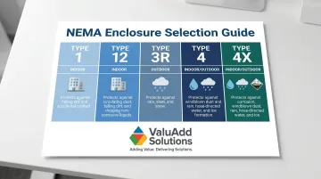
For corrosive or wash-down environments, ValuAdd's disconnect switches carry NEMA Type 4X and 12 ratings with UL Listing.
Non-Negotiables:
- Do not begin installation if the upstream circuit cannot be confirmed de-energized
- Do not install a switch with a lower ampere or HP rating than required
- Do not proceed without confirming local AHJ permit requirements
Tools and Parts Required
Essential Tools:
- Non-contact voltage tester
- Torque screwdriver or torque wrench (set to terminal manufacturer specs)
- Conduit bender and fish tape
- Wire strippers
- Crimping tool for ring terminals
- Screwdrivers (flat and Phillips)
- Drill with bits for enclosure mounting
Essential Parts:
- Rated disconnect switch in the correct NEMA enclosure
- Appropriately sized conductors (matching the circuit's ampacity requirements)
- Conduit and fittings
- Wire labels or heat-shrink markers
- Lockout hasp and padlock for LOTO
Situational Items:
- Fuse pullers and spare fuses (for fusible switch types)
- Insulated gloves rated for the system voltage
- Multimeter for post-installation continuity checks
How to Install a Disconnect Switch (Step-by-Step)
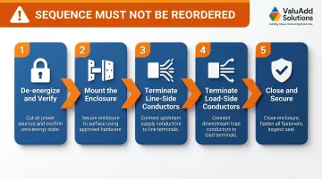
The following sequence must not be reordered. All mechanical work must be completed before any conductors are connected, and power must not be restored until validation checks are complete.
Step 1 — De-energize and verify:
Open the upstream breaker or disconnect feeding this circuit. Apply LOTO devices, then test all conductors at the intended switch location with a voltage tester to confirm zero energy state before touching any wiring.
Step 2 — Mount the enclosure:
Secure the disconnect switch enclosure to a wall, panel, or structural support at the correct height and within sight of the motor. Use appropriate fasteners for the surface material and verify the enclosure is level and stable. Run and secure conduit into the enclosure's knockouts before pulling wire.
Step 3 — Terminate line-side (incoming) conductors:
Pull the incoming supply conductors through the conduit into the enclosure. Connect each phase conductor to the corresponding line-side (top) terminal of the switch following the manufacturer's terminal diagram. Tighten each lug to the torque value stated on the switch nameplate or installation sheet. Do not estimate. NEC 110.14(D) explicitly requires the use of calibrated torque tools.
Step 4 — Terminate load-side (outgoing) conductors:
Connect the conductors running to the motor or equipment to the load-side (bottom) terminals of the switch in the same phase sequence. Apply wire labels at both ends identifying the circuit. Ensure no conductor insulation is pinched under terminal lugs and that no bare copper is exposed outside the lug.
Step 5 — Close, secure, and prepare for testing:
Route any ground conductor to the enclosure ground lug. Verify no tools, wire offcuts, or debris remain inside the enclosure. Close and latch the enclosure door. Remove LOTO devices only after confirming all personnel are clear and the installation is complete.
Post-Installation Checks and Validation
Functional Test Sequence:
With upstream power restored, use a voltage tester to confirm line-side voltage is present at the switch input. Then, with the switch in the OPEN (off) position, verify that load-side terminals read zero voltage, confirming the switch is isolating the downstream circuit.
Operational Close Test:
Operate the switch handle to the CLOSED (on) position. Confirm load-side voltage is now present and matches line voltage. Verify the connected motor or equipment starts and runs normally. Listen for arcing sounds or observe for sparking, which indicate a loose connection or wiring error.
Temperature Verification:
Correct installation produces no abnormal heat at terminals within the first 15–30 minutes of operation. Use an infrared thermometer or thermal camera to check terminal temperatures. NFPA 70B (2023) now mandates documented infrared thermography inspections at normal circuit loading, with Delta-T (ΔT) measurements between the hot terminal and a nearby reference terminal.
Any terminal running significantly hotter than adjacent ones signals a bad connection that requires immediate correction before continued operation.
Why Validation Cannot Be Skipped:
Many wiring errors only manifest under load. A connection that passes a no-load visual check can arc and overheat under motor starting current, leading to insulation damage, tripped upstream protection, or fire.
Common Installation Problems and Fixes
Loose or Under-Torqued Terminal Connections
Problem: Intermittent power loss to the motor, unexplained tripping of upstream breakers, or visible discoloration/burn marks at switch terminals.
Terminal screws often back off over time from thermal cycling during repeated motor starts, and hand-tightening without a torque tool leaves connections under-spec from day one. Contact surface oxidation then increases resistance, generating the heat that causes discoloration and tripping.
Fix: Apply LOTO, then re-torque all terminals to the manufacturer's specified value. If lug threads or conductor strands show heat damage, replace those components before re-energizing.
Wrong NEMA Enclosure for the Environment
Problem: Corrosion on internal components, moisture visible inside the enclosure, or switch handle operating stiffly after a short service period.
A NEMA Type 1 (general indoor) enclosure installed in a washdown area, outdoor location, or dusty manufacturing environment will degrade quickly — it was never rated for those conditions.
Fix: Replace with the correct NEMA rating for the installation environment (typically NEMA 4X for washdown or corrosive areas, NEMA 12 for dusty industrial settings). Before reinstalling:
- Inspect all internal components for corrosion damage
- Confirm gaskets and seals on the replacement enclosure are intact
- Verify the new enclosure's rating is marked on the label
Incorrect Ampere or HP Rating
Problem: The switch handle is difficult to operate, the switch runs hot during normal motor operation, or fuses blow on motor starts (for fusible types).
This usually traces back to sizing the disconnect on running current alone — skipping the 115–125% FLA multiplier, ignoring motor starting surge, or overlooking the switch's HP rating requirement.
Fix: Pull the motor nameplate FLA and HP, then cross-reference against the installed switch's ampere and HP ratings. If the switch is undersized, replace it with a correctly rated unit. Do not attempt to work around an undersized switch by adjusting upstream protection.
Pro Tips for Installing a Disconnect Switch Effectively
Use Two Independent Voltage Checks
Always verify zero voltage with two independent checks — a non-contact tester and a solenoid (wiggy) tester — before touching any conductor. A single tester can fail, and in industrial environments this check takes seconds but can save lives.
Maintain Phase Sequence Consistency
Keep phase sequence consistent from line-side terminals through to the load-side. Mislabeled or transposed phases will cause three-phase motors to run in reverse, which on pumps and compressors can cause immediate damage.
Document the Installation As-Built
Photograph the internal wiring before closing the enclosure. Record the switch model, ratings, and torque values applied. Label the enclosure externally with the circuit ID and upstream overcurrent device location. That documentation cuts troubleshooting time significantly during future maintenance calls.
Know When to Stop and Call a Licensed Electrician
If the upstream feeder cannot be fully de-energized, if the system voltage exceeds your team's training level, or if the local AHJ requires a licensed contractor to pull the permit, do not proceed.
A failed inspection or arc flash incident will cost far more than qualified labor. According to Bureau of Labor Statistics data, the national mean hourly wage for electricians is $32.60 — a fraction of the liability exposure from an improper installation.
Conclusion
A disconnect switch is a safety-critical component—its entire purpose is to reliably isolate energy during maintenance or emergencies. Every step matters: switch selection, torque verification per NEC 110.14(D), and post-installation testing each directly affect whether the switch performs under real fault conditions.
Treat this installation as an opportunity to build in long-term reliability. Three habits make the difference:
- Document all wiring, torque values, and inspection dates at the time of installation
- Use correctly rated, certified components matched to your load and enclosure requirements
- Schedule periodic re-torque checks and enclosure integrity inspections as part of routine maintenance
For switch selection, compliance verification, or installation guidance, ValuAdd's technical team can help identify the right UL Listed, NEMA Type 4X or 12 rated disconnect for your specific application.
Frequently Asked Questions
What is the correct procedure to operate (throw) a disconnect switch?
To open (disconnect), confirm the load is de-energized or verify the switch is rated for load-break operation, then move the handle firmly to the OFF position in a single deliberate motion. To close, move the handle to ON with equal decisiveness; hesitating mid-stroke on a load-break switch can cause arcing damage.
How much does it cost to install a disconnect switch?
Installation cost varies by system complexity, switch rating, and local labor rates. A qualified electrician typically charges $65–$130 per hour for a standard 30A–100A motor disconnect installation, including materials and permit fees.
What size disconnect switch do I need for my motor?
The switch ampere rating must be at least 115% of the motor's full-load ampere (FLA) rating from the nameplate per NEC 430.110. The switch must also carry a horsepower (HP) rating equal to or greater than the motor's HP.
What is the difference between a fusible and non-fusible disconnect switch?
A fusible disconnect includes fuse holders for overcurrent protection within the switch itself; a non-fusible (solid-blade) disconnect provides isolation only and relies on upstream overcurrent devices. Choose fusible types where dedicated short-circuit protection is required at the motor location.
Do I need a permit to install a disconnect switch?
Permit requirements vary by jurisdiction, but most local authorities require an electrical permit for new disconnect switch installations—especially when new branch circuits or feeder taps are involved. Always check with the local AHJ before starting work to avoid failed inspections or insurance complications.
Can a disconnect switch be used as the sole motor controller?
No. A disconnect switch is an isolation device, not a motor controller. NEC Article 430 requires a separate motor controller (such as a contactor, starter, or VFD) for starting and stopping the motor under normal operating conditions. The disconnect is only intended to isolate the motor for maintenance or emergency shutdown.