Introduction
In a data center or mission-critical facility, even a fraction-of-a-second power interruption can corrupt financial transactions, crash virtualized server clusters, or halt life-support systems. A single voltage sag lasting 20 milliseconds (the time it takes to blink) can cascade into six-figure revenue losses or compliance violations. Transfer switch selection in these environments directly determines whether your facility maintains continuity during an outage — or fails to.
This guide covers the types of transfer switches deployed in data centers, how transition modes differ in their impact on IT loads, the design and specification requirements that separate compliant installations from code violations, and the NFPA, NEC, and UL standards that govern these systems.
TLDR:
- Data centers require transfer times within the 20 ms dropout tolerance of IT equipment per the ITIC curve
- Static Transfer Switches (STS) deliver sub-4 ms transitions for Tier III/IV; closed-transition ATS pairs with UPS for load protection
- UL 1008 Withstand and Closing Ratings (WCR) are mandatory—undersized switches fail during faults
- 4-pole switched neutral prevents ground fault nuisance trips in separately derived generator systems
- Bypass-isolation ATS enables maintenance without interruption, as required by NFPA 110 for mission-critical sites
Why Data Centers Have Unique Transfer Switch Requirements
Unlike commercial or residential applications, data centers operate under near-zero tolerance for power interruptions. Servers, storage arrays, and networking equipment are sensitive to sub-cycle voltage sags. The ITIC (CBEMA) curve defines the AC input voltage tolerance envelope that Information Technology Equipment can withstand: a complete voltage dropout must resolve within 20 milliseconds to prevent equipment failure.
That makes the acceptable transfer window dramatically narrower than in conventional facilities—where a 100 ms interruption might only dim lights, it would crash database servers in a data center.
Data center power architecture shapes every transfer switch requirement. The typical topology includes:
- UPS systems providing battery-backed ride-through during utility-to-generator handoff
- Power Distribution Units (PDUs) feeding redundant circuits to racks
- Redundant utility feeds from separate substations or grid entry points
The transfer switch must hand off load to a backup source within the UPS hold-up window—typically 10–20 minutes at full load for enterprise-class systems—while not introducing voltage transients, frequency deviations, or phase disturbances that could trip downstream equipment protection or overwhelm server power supply tolerances.
How Uptime Tier Classifications Drive Transfer Switch Requirements
Uptime Institute Tier classifications directly influence redundancy requirements and the type and quantity of transfer switches:
| Tier Level | Redundancy Requirement | Transfer Switch Implication |
|---|---|---|
| Tier III | Concurrently Maintainable | Bypass-isolation ATS; components removable without load impact |
| Tier IV | Fault Tolerant | 2N fully duplicated power paths; independent ATS per path |
Tier III facilities require the ability to perform maintenance on transfer switches without dropping load, driving the need for bypass-isolation configurations. Tier IV mandates that a single equipment failure—including ATS failure—cannot impact operations, requiring fully redundant transfer switches in physically isolated power distribution paths.
Types of Transfer Switches Used in Data Centers
Automatic Transfer Switches (ATS)
ATS units form the backbone of most data center backup power schemes, monitoring utility voltage and frequency continuously through microprocessor-based controllers.
Upon detecting an out-of-tolerance condition (typically 10–15% voltage deviation or frequency drift beyond ±0.5 Hz), the controller signals the standby generator and transfers load once output stabilizes — typically within 10–20 seconds of cranking.
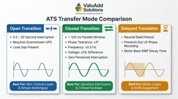
Three ATS transition modes are relevant to data centers:
Open transition (break-before-make): Creates a brief interruption of 0.5–30 seconds depending on generator startup time. Acceptable only when downstream UPS systems bridge the gap during generator stabilization.
Closed transition (make-before-make): Momentarily parallels sources for under 100 ms, achieving zero perceived interruption. Requires tight synchronization (±5° phase angle, ±0.2 Hz frequency, ≤5% voltage difference) — preferred for sensitive IT loads and live generator testing.
Delayed transition: Includes a neutral dwell period (center-off position) allowing residual motor voltage decay. Less common in pure IT environments but essential for large computer room air handlers (CRAHs) and chilled water pumps to prevent out-of-phase reclosing that damages motor windings.
Static Transfer Switches (STS)
Static Transfer Switches use solid-state devices (SCRs or IGBTs) with no mechanical contacts, achieving transfer times under 4 milliseconds — within the ride-through capability of modern IT power supplies. STS units are typically deployed downstream of UPS systems in the power distribution path, providing an additional redundancy layer by switching between two independent UPS-fed sources (not a generator-to-utility switch).
Two primary STS algorithms dominate data center deployments:
| Algorithm | Transfer Time | Application |
|---|---|---|
| Power or Gate (POG) | ≤4 ms (¼ cycle) | Standard IT loads; transfers as quickly as possible without paralleling sources |
| Volt-Second Synchronization (VSS) | ≤8 ms (½–¾ cycle) | Downstream transformers; controls magnetic inrush by balancing volt-seconds across the transition |
Both algorithms complete transfers well within the 20 ms ITIC dropout tolerance, making STS the preferred solution for Tier III/IV facilities where UPS-level continuity is needed at the distribution layer (typically 480V PDU input or 208V branch circuit distribution).
Manual Transfer Switches (MTS)
MTS units require human intervention and are unsuitable for primary data center backup paths. They may appear in maintenance bypass configurations or for non-critical ancillary systems (perimeter lighting, loading dock equipment, office HVAC) where a brief, planned outage is acceptable. Attempting to use MTS for critical IT loads violates NEC Article 700 requirements for automatic operation of emergency systems.
Transfer Transition Types: What Data Centers Actually Need
Open Transition (Break-Before-Make)
The load is disconnected from Source A before connecting to Source B, creating an interruption measured in cycles (typically 0.5–30 seconds depending on generator startup time). This is only viable in data centers when a UPS is downstream to cover the gap. Without a UPS buffer, open transition will cause equipment dropout. Server power supplies, even with power factor correction, cannot ride through multi-second interruptions.
When open transition is acceptable:
- Downstream UPS provides ≥15 minutes runtime at design load
- Generator starts and stabilizes within 10 minutes
- IT equipment is protected by the UPS; only building infrastructure sees the transfer gap
Closed Transition (Make-Before-Make)
Both sources are momentarily paralleled (typically under 100 ms), requiring source synchronization. ASCO/Schneider controllers enforce tolerances of ±5 electrical degrees phase angle, ±0.2 Hz frequency, and ≤5% voltage difference. If sources fail to synchronize within the programmed window (adjustable from 1 to 60 minutes), the controller either aborts the closed transition or defaults to open transition.
This is the preferred ATS transition type for:
- IT loads where no UPS is present (rare in modern data centers)
- Testing generator readiness without disrupting operations (monthly NFPA 110 tests)
- Transferring back to utility after an outage (return transfer) with zero downtime
Why synchronization matters: Connecting two out-of-phase AC sources creates inrush currents exceeding 10x normal load, which can weld contacts, trip protective relays, or damage transformer windings. Microprocessor controllers prevent this by sampling voltage waveforms hundreds of times per second, closing contacts only when sources are electrically aligned.
Static Transfer Switches vs. Closed-Transition ATS
The decision comes down to how much voltage deviation your loads can tolerate during a transfer. Server power supply holdup time is the key variable.
Modern server power supplies (80 PLUS Platinum/Titanium rated) typically include 20–40 milliseconds of holdup time, energy stored in DC bus capacitors that sustains output during input voltage dropout. The ITIC curve allows up to 20 ms of complete interruption. A closed-transition ATS, which parallels sources for 50–100 ms, falls outside this window if the transfer creates any voltage sag.
STS is required when:
- Load cannot tolerate even momentary voltage deviation (high-frequency trading systems, medical imaging)
- Tier III/IV concurrent maintainability requires redundant power paths deeper in the distribution chain
- Switching between two UPS-fed sources at the PDU or rack level for maximum uptime
Closed-transition ATS suffices when:
- UPS is upstream and provides ride-through during any ATS operation
- Monthly generator testing must occur without impacting production (closed transition allows in-service testing)
- Budget constraints make STS deployment at every distribution point impractical
In-Phase Transfer for Motor-Heavy Ancillary Loads
STS addresses IT load sensitivity, but motor-heavy ancillary systems require a different approach entirely. Computer room air handlers, centrifugal chillers, and condenser water pumps all need delayed transition to prevent out-of-phase reclosing. When a motor is de-energized, residual magnetic flux keeps the rotor spinning and generating back-EMF (counter-voltage). Reconnecting power while this residual voltage is out of phase with the incoming source creates mechanical shock loads exceeding 300% of normal starting torque. This can shear couplings or damage motor windings.
Solution: Delayed-transition ATS with adjustable neutral dwell time (0.5–5 seconds) allows residual voltage to decay below 25% of nominal before reconnecting, ensuring safe motor re-acceleration.
Key Design and Specification Requirements
Transfer Time and Load Capacity
The transfer switch must be rated to carry 100% of the connected load continuously, plus a design margin. Industry practice recommends sizing ATS units for 125% of intended load or using 100%-rated upstream circuit breakers to comply with NEC continuous loading limits (80% of breaker rating for 3+ hour operation). The switch's ampere rating—not just the upstream breaker—determines capacity.
Critical specification error: Specifying an ATS rated at 400A when the calculated load is 390A. Under NEC 210.20(A), continuous loads require 125% sizing: 390A × 1.25 = 487.5A minimum ATS rating required. The correct selection is a 600A ATS.
Withstand and Closing Rating (WCR)
UL 1008 mandates that transfer switches be tested and rated for the available fault current at their installation point. Transfer switches are not rated to clear faults—they must withstand them until an upstream Overcurrent Protective Device (OCPD) trips.
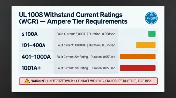
UL 1008 WCR Minima:
| Switch Rating (Amps) | Minimum Current (Amps) | Minimum Duration (Seconds) | Power Factor |
|---|---|---|---|
| 100 or less | 5,000 | 0.008 | 0.40–0.50 |
| 101–400 | 10,000 | 0.025 | 0.40–0.50 |
| 401–1000 | 20× rating (min 10,000) | 0.050 | 0.25–0.30 |
| 1001+ | 20× rating | 0.050 | 0.20 or less |
The 7th Edition of UL 1008 replaced "Any Breaker" ratings with specific time-based ratings. Engineers must verify that the upstream breaker's instantaneous clearing time is less than or equal to the ATS marked duration. Selecting a switch with insufficient WCR results in catastrophic failure during a fault event—contacts welding closed, enclosure rupture, or fire.
Non-negotiable: This is a compliance requirement enforced by Authorities Having Jurisdiction (AHJs), not just a performance specification.
Neutral Conductor Handling
In data centers fed by separately derived sources—where the generator output creates a new neutral-to-ground bond per NEC 250.30(A)—incorrect neutral handling causes ground fault protection nuisance trips or, worse, neutral-to-ground voltage that disrupts communication circuits and creates shock hazards.
Three neutral configurations:
| Configuration | Description | Application |
|---|---|---|
| Solid Neutral (3-Pole) | Neutral remains connected between sources | Cannot reliably route fault currents; may cause GFP nuisance trips |
| Switched Neutral (4-Pole) | Breaks neutral during transfer | Required for separately derived generator systems per NEC 250.30(A) |
| Overlapping Neutral (4-Pole) | Momentarily connects neutrals (<100 ms) before breaking | Prevents voltage transients during switching; maintains accurate GFP |
Best practice for data centers: 4-pole ATS with overlapping neutral. This configuration prevents the momentary loss of neutral reference that can create 208V phase-to-ground faults on 120V branch circuits during transfer, while still isolating grounds for accurate ground fault sensing.
Controls, Monitoring, and Communication
Data center ATS units require microprocessor-based controllers capable of:
- Event logging: Timestamp records of every transfer, source quality deviation, and generator start
- Remote monitoring: Standard industrial protocols (Modbus RTU/TCP, BACnet/IP, SNMP)
- DCIM integration: Direct data exchange with Data Center Infrastructure Management platforms for centralized visibility
- Programmable logic: Adjustable transfer thresholds, time delays, and load-shedding sequences
This is an operational requirement, not a convenience. Without integration into monitoring systems, operators cannot detect pre-failure conditions (contact wear, control voltage drift) or perform root-cause analysis after outages.
ValuAdd supplies IEEE 519-compliant, UL Listed electrical components and integrated control panel designs for monitored power distribution in data center environments. Products like the ATyS FT transfer switch include the ATyS C66 controller with RS485 Modbus support, enabling integration into DCIM platforms for real-time status monitoring and remote transfer control—critical capabilities for system integrators building compliant data center power architectures.
Compliance Standards That Govern Data Center Transfer Switches
NEC Article 700/701/702 Requirements
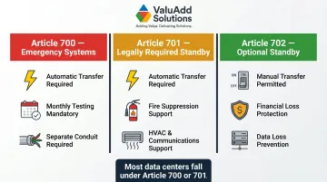
Three National Electrical Code articles impose different requirements based on system classification:
| NEC Article | System Type | Transfer Switch Requirements |
|---|---|---|
| Article 700 | Emergency Systems (life safety) | Automatic transfer; monthly testing; separate conduit/raceway from normal power |
| Article 701 | Legally Required Standby | Automatic transfer; supports fire suppression, HVAC, communications systems |
| Article 702 | Optional Standby Systems | May use manual transfer; protects against financial loss or data center downtime |
Most data centers fall under Article 700 or 701 depending on jurisdiction and whether they host healthcare records, financial trading systems, or other legally protected data. Healthcare data centers serving electronic health record (EHR) systems must comply with Article 700 emergency system requirements, mandating automatic transfer and required testing protocols.
NFPA 110 Testing and Bypass-Isolation Requirements
NFPA 110 mandates regular testing of transfer switches:
- Monthly testing: Electrically operate the switch from primary to alternate position and back (Section 8.4.6)
- Annual full-load testing: Transfer actual connected load to generator for minimum 1.5 hours
- Triennial comprehensive testing: Full load bank testing and inspection (Level 1 EPSS installations)
Bypass-Isolation Requirement: NFPA 110 Class X systems—where a single outage poses serious life safety or financial risk—require bypass-isolation capability. This allows the primary ATS mechanism to be isolated and removed for maintenance while the load remains energized through a built-in bypass path. The Socomec ATyS FT transfer switch, available through ValuAdd, provides bypass-isolation configurations rated up to 400A — a practical option for installations where NFPA 110 Class X compliance is required.
UL 1008 and IEC 60947-6-1 Listing
UL 1008 is the primary listing standard for transfer switches up to 1000V in non-hazardous locations in North America. Specifying a UL 1008-listed ATS is the baseline compliance requirement for any U.S. data center installation. UL 1008 listing verifies:
- Withstand ratings under fault conditions
- Endurance testing (minimum 6,000 mechanical operations)
- Temperature rise limits
- Dielectric withstand voltage
IEC 60947-6-1 serves as the international equivalent for global deployments. Data centers with multinational operations should verify that transfer switches carry both certifications to simplify approvals across jurisdictions.
Redundancy and Bypass-Isolation Configurations
Bypass-Isolation ATS
A bypass-isolation transfer switch includes a built-in bypass switch that allows the primary ATS mechanism to be isolated and removed for maintenance or replacement while the load remains energized through the bypass path. In Tier III/IV data centers, this capability is mandatory—maintenance cannot interrupt the load.
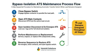
How it works:
- Close bypass switch to parallel ATS contacts
- Open ATS main contacts (load now flows through bypass only)
- Open isolation disconnect to de-energize ATS for safe maintenance
- Perform maintenance or replacement
- Reverse sequence to restore ATS to service
NFPA 110 Class X systems—where downtime exceeds acceptable risk thresholds—require this capability. Without bypass-isolation, every ATS maintenance event forces either a load transfer to redundant paths or a full facility shutdown.
Redundant ATS Configurations
Data center redundancy topologies directly map to Uptime Institute Tier requirements:
N+1 Configuration
- Deploys one additional ATS for every N units in service
- Single ATS failure does not impact operations
- Maintenance requires shifting load to the redundant unit
- Standard for Tier II+ facilities
2N Configuration (Fully Duplicated)
- Two completely independent power paths, each with a dedicated ATS
- A+B power distribution feeds dual-corded IT equipment
- Allows maintenance on an entire power path without load impact
- Required for Tier IV fault tolerance
Coordinating with Paralleling Switchgear
In multi-generator data centers, transfer switches coordinate with paralleling switchgear to manage load sharing and generator sequencing. The ATS control logic must interface with the generator management system to:
- Prevent load transfer until all paralleled generators reach stable voltage and frequency
- Execute load-shedding sequences during partial generator availability
- Coordinate with utility breaker interlocks to prevent backfeed
Getting this right requires tight coordination between the electrical engineer, ATS manufacturer, and generator vendor. Poorly programmed sequencing can trigger failed transfers, generator overload, or utility backfeed violations—any of which can take a data center offline.
Frequently Asked Questions
What is ATS in data center?
An ATS (Automatic Transfer Switch) in a data center automatically detects loss of utility power and transfers the electrical load to a backup source—typically a generator—without human intervention. The controller monitors voltage and frequency continuously, signaling the generator to start and completing the transfer once backup power stabilizes.
What is the difference between an ATS and a UPS?
A UPS (Uninterruptible Power Supply) provides instantaneous battery-backed power during the brief gap between an outage and generator startup, while an ATS handles the actual switching of power sources. The two work together: the UPS bridges the 10–20 second transfer gap that the ATS creates during source changeover, preventing any interruption to IT equipment.
What is the difference between ATS and STS in data center?
An ATS typically uses electromechanical switching with transfer times of 10–20 seconds (suitable when paired with a UPS), while a Static Transfer Switch (STS) uses solid-state components to transfer in under 4 milliseconds. STS is deployed deeper in the distribution path—at the rack PDU level—for loads that cannot tolerate any interruption even with a UPS in place, providing redundancy between two UPS-fed sources.
What is a 3-phase ATS?
A 3-phase ATS switches all three phases simultaneously between sources, which is standard for data centers and industrial applications where three-phase power feeds large UPS systems, PDUs, and HVAC equipment. Units with a switched fourth pole (neutral) are required when the generator establishes a new neutral-to-ground bond per NEC 250.30(A).
Is it illegal to run a generator without a transfer switch?
Yes. The NEC and most local codes require a permanent transfer switch when connecting a generator to a building's electrical system. Operating without one risks backfeed into the utility grid, endangering utility workers, and can void warranties and insurance coverage. Manual breaker interlocking does not satisfy NEC Article 700 requirements for automatic emergency system operation.