Introduction
When utility power fails at a data center, operators have seconds—not minutes—to prevent catastrophic losses. According to the Uptime Institute's 2025 Annual Outage Analysis, 54% of data center operators report their most recent significant outage cost more than $100,000, with one in five exceeding $1 million. That translates directly to lost revenue, breach penalties, and damaged customer relationships.
Most impactful outages trace back to power issues, and 20% of facility managers have experienced a transfer switch failure in the past five years — 42% of which caused complete facility power loss.
Transfer switches sit at the decision point between uptime and disaster. Whether automatic or static, they determine if IT equipment rides through a seamless source transition or absorbs an interruption that compounds into six-figure losses.
Understanding these systems is the first step to building a resilient power strategy. This guide covers how Automatic Transfer Switches (ATS), Static Transfer Switches (STS), Power Distribution Units (PDUs), and redundancy architectures protect data center operations when primary power fails.
Key Takeaways
- ATS switches power in 50–200ms using mechanical contacts; STS switches in under 4ms using solid-state thyristors
- Transfer switches automatically reroute loads to backup sources (generators or secondary UPS feeds) when primary sources fail
- PDUs distribute UPS power to server racks, while PDCs aggregate power upstream for entire data halls
- N+1 and 2N redundancy designs rely on correctly specified transfer switches to eliminate single points of failure
- Verify UL 1008, IEEE 519, and Class E2 compliance before specifying any mission-critical switching gear
How Power Flows Through a Data Center
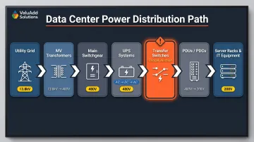
Data centers receive incoming power at medium voltage—typically 13.8 kV or 34.5 kV—directly from the utility grid. Step-down transformers reduce this to 480V or 400V for main switchgear and UPS systems. Downstream PDU transformers further step voltage to 208V or 120V for server racks.
The complete power flow path:
- Utility grid (medium voltage)
- Medium-voltage transformers
- Main switchgear
- UPS systems (AC→DC→AC double conversion)
- Transfer switches ← Critical junction point
- PDUs/PDCs
- Server racks and IT equipment
Transfer switches sit between primary and backup power sources. That single decision point determines whether IT loads experience an interruption during source transitions. In a standard double-conversion UPS design, input AC charges battery banks (rectification), which then power the output inverter (converting back to AC).
The final AC-to-DC conversion happens inside each server's power supply unit.
Most data centers operate on AC power throughout the distribution chain until the server PSU stage. When utility power degrades or fails, generator backup systems provide the alternate AC source — and transfer switches are what route loads to it cleanly.
What Are Data Center Transfer Switches and Why They Matter
A transfer switch is a device that detects failure or degradation in the primary power source and automatically connects the load to an alternate source—utility feed, generator, or second UPS—without manual intervention. UL 1008 governs the design, testing, and certification of transfer switch equipment, ensuring components work together safely under fault conditions.
Three Transfer Transition Types
Transfer switches execute one of three transition modes depending on load sensitivity and source availability:
Open Transition (Break-Before-Make):
- Disconnects from source A before connecting to source B
- Brief power interruption (typically 50–200ms)
- Simplest design with lowest cost
- Suitable when UPS bridges the gap
Closed Transition (Make-Before-Make):
- Connects to source B before disconnecting from source A
- Momentary paralleling of both sources (<100ms)
- Seamless transfer with no interruption
- Requires synchronized sources or sophisticated control logic
Soft Loading:
- Gradual load transfer for generator synchronization
- Prevents sudden inrush currents that stress generators
- Used when transferring large motor loads or when the generator needs time to stabilize frequency
Generator Handoff Sequence
When utility power fails, the transfer switch sends a start signal to the standby diesel generator. Generators require 5–30 seconds to reach stable voltage and frequency. During this window, the UPS system provides uninterrupted power to IT loads. This handoff sequence is where most failures occur — typically when equipment specifications don't account for actual startup times and real load-transfer demands.
NFPA 110 Type 10 classifications require emergency power restoration within 10 seconds, making UPS ride-through capacity a critical design parameter. Where transfer switches are physically deployed determines which loads they protect — and how granularly engineers can isolate faults.
Where Transfer Switches Sit in the Power Chain
Transfer switches deploy at two primary points in data center electrical architecture:
Medium-Voltage Level (Facility Protection):
- Protects entire building feeds upstream of transformers
- Switches between dual utility feeds or utility-to-generator
- Requires Class E2 load-break ratings for high fault currents
- Governed by NEC Article 708 (Critical Operations Power Systems)
Low-Voltage/PDU Level (Load Protection):
- Protects individual data halls or critical equipment groups
- Switches between dual UPS outputs or UPS-to-generator
- Enables zone-level isolation and maintenance
- Classified under NEC Articles 700 (Emergency), 701 (Legally Required Standby), or 702 (Optional Standby)
Larger Tier III and Tier IV data centers deploy transfer switches at both layers, creating defense-in-depth against single-point failures. This layered approach means a fault at the utility feed level doesn't cascade into individual power zones — and maintenance on one layer doesn't require taking the entire facility offline.
ATS vs. STS: Key Differences, Use Cases, and Selection Guide
The right transfer switch depends on two variables: how fast you need to switch, and whether your backup source is live when you need it.
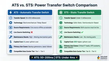
An Automatic Transfer Switch (ATS) is an electromechanical device that transfers loads between two power sources in 50–200 milliseconds (3–12 cycles at 60 Hz per UL 1008). That brief interruption is tolerable when UPS systems bridge the gap during generator startup or when switching to a secondary utility feed.
A Static Transfer Switch (STS) uses thyristors (silicon-controlled rectifiers) to transfer between two live, synchronized sources in under 4 milliseconds—often less than one electrical cycle. That near-instantaneous speed eliminates interruptions for zero-tolerance loads like financial trading systems, telecom infrastructure, or healthcare-adjacent data centers where even a single-cycle gap causes operational failures.
Head-to-Head Comparison
The table below covers the variables that matter most for data center specification.
| Feature | ATS (Automatic Transfer Switch) | STS (Static Transfer Switch) |
|---|---|---|
| Transfer Speed | 50–200 milliseconds | <4 milliseconds (sub-cycle) |
| Technology | Electromechanical contacts | Solid-state thyristors (SCRs) |
| Source Requirements | Single backup source (generator or second utility feed) | Two live, synchronized sources |
| Live Source Switching | No—backup must stabilize before transfer | Yes—switches between two hot sources instantly |
| Maintenance | Periodic contact inspection; mechanical wear over time | Minimal—no moving parts |
| Cost | Lower capital cost | 2–3× ATS cost |
| Use Cases | Generator-backed systems, UPS-protected loads | Dual-corded servers, zero-interruption requirements |
| Data Center Tier | Tier I–III (when combined with UPS) | Tier III–IV (fault-tolerant designs) |
When to Choose ATS vs. STS
Choose ATS when:
- Backup source is a diesel generator (not live until started)
- UPS systems provide sufficient ride-through during the 50–200ms transfer window
- Cost sensitivity is a primary concern
- Load can tolerate brief interruptions (<100ms)
- NEC Article 702 (Optional Standby) applies
If your architecture uses dual live feeds, STS becomes the right call:
Choose STS when:
- Two live UPS feeds are available and synchronized
- Load is zero-tolerance for interruption (financial services, hyperscale, real-time processing)
- Tier IV fault tolerance is required
- Dual-corded servers need instantaneous failover between independent power paths
- NEC Article 700 (Emergency Systems) mandates seamless transfer
One specification error to avoid: STS requires two live, synchronized power sources. Without dual live feeds, it offers no advantage over ATS and adds cost without benefit. Transfer times can extend to 8ms when sources are out of phase and Volt-Second Synchronizing algorithms compensate for frequency drift. Verify actual performance specifications under real-world load conditions before finalizing your design.
ValuAdd supplies UL Listed, Class E2 load break compliant transfer switching components for both ATS and STS applications. Certified equipment matters here—performance specs printed on a datasheet need to hold under actual load conditions, not just controlled test environments.
Power Distribution in Data Centers: PDUs, PDCs, and Beyond
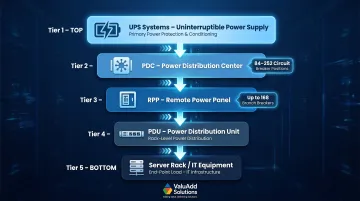
Power Distribution Unit (PDU): A PDU receives high-capacity input from a UPS or switchgear and distributes it via individual circuit breakers to server racks. Basic models handle simple power distribution without monitoring.
Intelligent PDUs — now standard in Tier III/IV facilities — add metered circuits, remote switching, and real-time telemetry for current, voltage, and power consumption per outlet. Operators use this data to balance phase loads, track energy efficiency, and support predictive maintenance.
Power Distribution Center (PDC): A PDC aggregates power from the UPS and feeds multiple PDUs or Remote Power Panels (RPPs) across an entire data hall. These floor-mounted distribution hubs typically house 84–252 circuit breaker pole positions, sitting above individual PDUs in the power hierarchy.
Remote Power Panel (RPP): Compact distribution panels that sit between PDCs and rack-level PDUs, supporting up to 168 branch breakers. RPPs enable electrical capacity expansion without costly infrastructure rework. In large facilities, the hierarchy flows: UPS → PDC → RPP → PDU → Server Rack.
The Shift to Intelligent PDUs
Hyperscale operators and colocation providers deploy thousands of intelligent PDUs to:
- Monitor and transmit real-time current, voltage, and power data per circuit
- Automate load balancing across three-phase circuits to prevent imbalance
- Enable remote circuit switching for maintenance or troubleshooting
- Track energy consumption for billing and PUE (Power Usage Effectiveness) calculations
- Support remote firmware updates and SNMP integration
Proper sizing and placement across this hierarchy directly affects how well upstream transfer switches protect the load. Undersized distribution equipment creates bottlenecks that negate that protection; capacity planning must account for future growth and peak demand scenarios.
Transfer Switch Redundancy Architectures for Zero-Downtime Operations
N+1 and 2N Redundancy Models
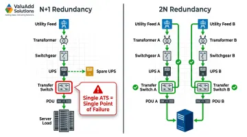
N+1 Redundancy
Provides one additional component for every required component to support full capacity. If four UPS units support the load, a fifth sits in reserve. While N+1 offers meaningful protection, a failure in the shared distribution path — including transfer switches — still risks interrupting operations.
2N (System Plus System)
Deploys two completely independent power paths, each with its own utility feed, transformer, switchgear, UPS, transfer switch, and PDU. Every critical load connects to both paths. A failure in one entire path does not interrupt operations because the second path continues unaffected.
Block Redundant (Catcher)
Uses a static transfer switch (STS) to move critical loads from a primary system to a reserve "catcher" system when faults occur. This approach enables higher facility utilization rates while maintaining protection.
Dual-Corded Server Strategy
These architectural models only hold up when server-level design matches them. Most enterprise servers include two power supplies, each connecting to separate PDUs on independent power paths with separate transfer switches upstream. This hardware-level redundancy only delivers its promise if:
- Each power path has its own transfer switch (not shared)
- Transfer switches are sized for full load (not N+1 sharing)
- Both paths remain synchronized or operate independently
- Maintenance procedures ensure one path stays live during work on the other
Eliminating Single Points of Failure
Even well-planned dual-corded deployments can fail at this step. A common design mistake is routing all loads through a single ATS — which makes the transfer switch itself the single point of failure. Mission-critical designs must treat the transfer switch as a redundant component, not just a protective one.
Design rule: In 2N architectures, deploy independent transfer switches for each power path. In N+1 designs, verify that transfer switch failure modes are covered by upstream or downstream redundancy — a single transfer switch cannot protect an entire facility.
Standards, Certifications, and Procurement Considerations
Specifying compliant transfer switches and distribution equipment ensures code compliance, insurance coverage, and predictable performance under fault conditions. The following standards govern data center power systems:
| Standard | Scope & Relevance |
|---|---|
| UL 1008 | Governs Automatic Transfer Switches (ATS). Verifies components work together to withstand short-circuit currents. Does not apply to static transfer switches. |
| UL 1008S | Covers Static Transfer Switches (STS). Separate standard for solid-state transfer equipment. |
| NFPA 70 NEC Articles 700/701/702 | Article 700: Emergency Systems; 701: Legally Required Standby; 702: Optional Standby. Defines installation requirements based on load classification. |
| NFPA 70 NEC Article 708 | Critical Operations Power Systems (COPS). Applies to facilities where power system failure results in life-threatening conditions or significant operational disruption. |
| NFPA 110 | Emergency and Standby Power Systems. Defines Class, Type (for example, Type 10 for 10-second restoration), and Level requirements for backup generators and transfer equipment. |
| IEEE 519 | Establishes voltage and current harmonic distortion limits at the Point of Common Coupling (PCC). Critical for UPS and VFD installations to prevent equipment damage. |
| TIA-942-C | Telecommunications Infrastructure Standard for Data Centers. Specifies minimum requirements for architecture, electrical design, mechanical systems, and redundancy. |
Understanding which standards apply to your installation is the first step. The checklist below translates those requirements into specific attributes to confirm before purchase.
Procurement Verification Checklist
When specifying transfer switches and distribution gear, verify:
- UL Listed designation: Confirms independent testing under fault conditions, not just normal operation
- IEEE 519 compliance: Ensures harmonic distortion stays within limits that protect sensitive IT equipment
- NEMA enclosure ratings: Type 12 for indoor dusty environments; Type 4X for outdoor or washdown applications
- Class E2 load break ratings: For medium-voltage switching applications, indicates high short-circuit making capacity (survives bolted fault closure without contact welding)
- Withstand and Closing Ratings (WCR): Must exceed available fault current at the installation point
Write specifications to the standard, not to vendor marketing claims. Require manufacturers to submit test reports and compliance statements for all critical ratings, including transfer time performance under both synchronized and unsynchronized conditions.
Frequently Asked Questions
What's the difference between STS and ATS?
ATS uses mechanical switching with 50–200ms transfer time, suitable for generator-backed systems where UPS provides ride-through. STS uses solid-state thyristors for sub-4ms transfer between two live, synchronized sources. That speed makes STS the right choice for zero-interruption loads like financial trading platforms or telecom infrastructure.
What are the two types of ATS?
Open transition (break-before-make) disconnects from the primary source before connecting to backup, causing a brief interruption. Closed transition (make-before-make) momentarily parallels both sources for seamless transfer, preferred where even 50–100ms gaps cause operational issues.
What is a data transfer switch used for?
A data center transfer switch automatically reroutes power from a failed or degraded primary source (utility feed) to a backup source (generator or second UPS feed) without manual intervention. This protects uptime for critical IT loads during outages or voltage disturbances.
What is the difference between PDC and PDU?
A PDC (Power Distribution Center) is a large upstream hub that aggregates UPS power and feeds multiple PDUs across a data hall. A PDU (Power Distribution Unit) sits downstream, connecting directly to individual server racks. PDCs sit higher in the distribution hierarchy; PDUs are the last step before the rack.
How is power supplied to data centers?
Power enters from the utility grid at medium voltage (13.8–34.5 kV), steps down through transformers, passes through switchgear and UPS systems, and reaches server racks via transfer switches and PDUs. Generators and battery backup provide redundancy at multiple points along this path.
What is power distribution in a data center?
Power distribution is the complete system of transformers, switchgear, UPS units, transfer switches, PDUs, and cabling that delivers conditioned power from the utility source to every piece of IT equipment. Proper design eliminates single points of failure and supports concurrent maintenance.