This guide is written for qualified electricians and plant or electrical engineers who are comfortable reading motor nameplates, working with NEC requirements, and navigating drive parameter menus. If that's you, what follows is a complete walkthrough — from selecting the right drive size to wiring, programming, and validating the installation before full-load operation begins.
Key Takeaways
- Size your VFD from the motor's Full Load Amps (FLA), not horsepower or kW
- Match the drive's duty class to your load: heavy duty for constant torque, normal duty for variable torque
- Verify voltage compatibility and de-energize before touching any terminals
- Program motor nameplate data first, then set acceleration/deceleration ramps before the first test run
- Run a no-load test followed by a loaded validation run — document both results
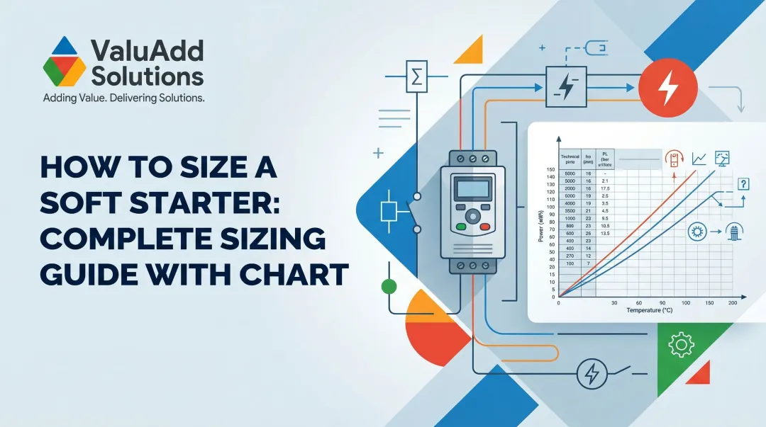
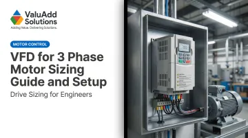
How to Size a VFD for a 3-Phase Motor
Start With Current, Not Horsepower
The core sizing rule is straightforward: the VFD's continuous output current rating must equal or exceed the motor's Full Load Amps from the nameplate. Horsepower or kW ratings are a starting point for filtering product catalogs, but they don't determine drive selection.
High-efficiency motors and multi-speed applications frequently draw less current at nameplate HP than older designs — meaning a drive sized by HP alone can be oversized or, in edge cases, undersized relative to actual current draw. Yaskawa's drive sizing form explicitly requests motor FLA, voltage, RPM, frequency, and service factor — not just horsepower.
ABB takes the same position in their ACS580 hardware documentation.
Constant Torque vs. Variable Torque
Load type determines which duty class you need:
- Constant torque loads (conveyors, compressors, extruders) demand full torque across the entire speed range. These require a heavy-duty rated drive. Rockwell's PowerFlex 520 heavy-duty rating, for example, provides 150% overload for 60 seconds — the threshold most constant-torque applications require for reliable startups and load transients.
- Variable torque loads (centrifugal pumps, fans, blowers) require torque only proportional to speed squared. Normal-duty ratings (110% overload for 60 seconds) are sufficient here.
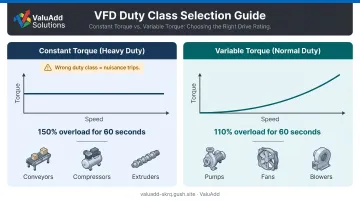
A normal-duty drive on a conveyor will trip repeatedly under load. An oversized heavy-duty drive on a fan wastes money and panel space.
ValuAdd's Benshaw H2 Series handles both through a dual-rating system — the same drive platform provides Normal Duty and Heavy Duty ratings, configurable for the application without requiring separate product lines.
Derating Factors You Cannot Skip
Three conditions force you to upsize to the next frame:
| Condition | Threshold | Effect |
|---|---|---|
| Ambient temperature | Above 45°C | Current derating required |
| Altitude | Above 1,000 m (3,300 ft) | Derating required up to 3,000 m |
| Carrier frequency | Increasing from base setting | Increases drive losses |
These thresholds come from Danfoss VLT HVAC Drive documentation — always pull the derating table from the specific drive manual rather than relying on generic rules of thumb.
Harmonics as a Sizing Consideration
Standard 6-pulse VFDs without input filtering can push total harmonic current distortion (THDI) above 100% at nominal load, according to ABB Technical Guide No. 6. Adding a large line reactor can reduce that to roughly 40% THDI — still a concern in facilities with shared transformers or sensitive instrumentation.
Where IEEE 519 compliance is required, specify a compliant drive from the start. ValuAdd's Benshaw H2 519/519P Series uses an 18-pulse design with phase-shifting transformer technology to achieve less than 8% THDv and 5% TDDi — meeting IEEE 519-2014 Table 1 and Table 2 requirements. For medium-voltage applications, the MVH2 and M2L Series use H-Bridge multi-level technology to produce a nearly perfect sine wave output with low harmonic content.
VFD Installation Prerequisites and Safety
What to Confirm Before You Begin
Before mounting or wiring anything, verify:
- **Supply voltage and phase configuration** match the drive's input specifications exactly
- Motor nameplate FLA, voltage, and frequency align with the drive's output range
- Enclosure NEMA rating matches the installation environment — NEMA 12 for indoor dust/drip protection, NEMA 4X for washdown, outdoor, or corrosive locations
ValuAdd's Benshaw SW Series Washdown Drives carry UL Type 4X (IP66) ratings for demanding environments. The H2 Series is rated NEMA 1/IP20 for standard indoor panels.
Safety Non-Negotiables
Three things must be in place before energizing:
- Upstream overcurrent protection — fuses or a circuit breaker rated per the manufacturer's specifications. Per Rockwell's PowerFlex 520 documentation, the drive provides Class 10 motor overload protection per NEC Article 430 but does not provide branch short-circuit protection. You must install upstream protection separately.
- Dedicated equipment ground — bond the drive chassis and motor frame to a common ground point. A dedicated ground conductor is mandatory.
- Adequate enclosure ventilation — if ambient temperature exceeds the drive's rated limit, do not proceed until cooling is resolved.
Tools and Materials Checklist
- Insulated screwdrivers and torque wrench (terminal torque specs vary by frame size — check the manual)
- Clamp meter for FLA verification during the loaded test run
- Shielded motor cable — ABB recommends symmetrically shielded VFD cable for optimal EMC performance and to reduce bearing current and motor insulation stress
- Wire labels
- Motor nameplate data and the VFD installation manual — both on hand before starting
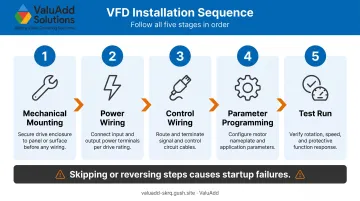
Step-by-Step VFD Setup for a 3-Phase Motor
Installation follows a fixed sequence: mechanical mounting → power wiring → control wiring → parameter programming → test run. Jumping ahead or reversing steps is one of the most common causes of startup failures and parameter mismatches.
Mounting and Enclosure Preparation
Mount the drive vertically on a flat, vibration-free surface. Rockwell PowerFlex 520 documentation specifies 50 mm (2.0 in.) top and bottom clearance and 25 mm (1.0 in.) side clearance for standard frames. Frame E with a control module fan kit requires 95 mm top and bottom.
For enclosure thermal calculations, use the drive's published power loss data rather than a generic efficiency estimate. Loss values are model- and frequency-specific, and a drive operating at higher carrier frequencies generates measurably more heat.
Power Wiring
Connect three-phase input power (L1, L2, L3) to the drive's input terminals. Connect motor leads (T1, T2, T3) to the output terminals. Use shielded cable for the motor run and terminate the shield at the drive end only.
Two critical warnings:
- Connecting input power to the output terminals destroys the drive immediately — no protection circuit prevents this
- Never install a contactor between the VFD output and the motor for routine switching. Rockwell explicitly states this can cause drive hardware damage. If motor isolation is required, interlock it with the drive's enable circuit.
Verify all terminal torque values with a torque wrench. Loose power connections are a leading cause of intermittent faults and fire risk. Confirm the ground conductor is landed at both the motor frame and the VFD ground terminal.
Initial Parameter Programming
With wiring complete and verified, power up the VFD once without the motor connected. Navigate to motor setup parameters and enter from the nameplate:
- Rated voltage
- Rated current (FLA)
- Rated frequency (60 Hz for North American installations)
- Rated RPM
- Service factor (note: NEMA MG 1 Part 31 specifies service factor 1.0 for inverter-fed motors — do not assume a higher sine-wave SF applies under VFD operation unless both motor and drive documentation confirm it)
Incorrect motor data causes the drive's overload protection and vector control algorithms to calculate incorrectly — which means the motor can be damaged while the drive reports no fault.
After entering motor data, set acceleration and deceleration ramp times. Short ramp times increase starting torque but add mechanical stress. Long ramp times reduce stress but keep the motor at low speed longer — a concern for standard TEFC motors, where shaft-mounted cooling fans run slower at reduced speeds.
For pump and fan applications, drives like ValuAdd's H2 Series offer integrated PID control with sleep/wake functions. Configure those features after basic motor data is confirmed and the drive is running stably.
For vector control modes, run the drive's auto-tune function with the motor unloaded and stationary before the first full-speed run. Rockwell's PowerFlex 520 supports both static and rotating tune — use rotating tune when the motor can be uncoupled for best results.
Post-Installation Checks and Validation
No-Load Test Run
Before energizing with the motor connected, do a visual inspection:
- No reversed wiring
- All terminal covers in place
- Shielded cable routed away from signal wiring
- Enclosure door secured
Then run the motor unloaded at low speed (10–20 Hz). Verify the motor rotates in the correct direction. If rotation is wrong, swap any two of the three motor output leads — never swap the input power leads.

Loaded Test and Documentation
Run the drive under actual load and verify output current matches the expected FLA range. Monitor for:
- Fault codes during or after startup
- Abnormal motor noise (resonance at specific frequencies — use skip-frequency bands to avoid continuous operation at resonant speeds)
- Excessive drive temperature after 10–15 minutes of operation
Skipping the loaded test is the most common commissioning shortcut, and it's the one most likely to cause a failure at production startup. Once the test is complete, document the results immediately.
Document everything before closing the enclosure:
- Final parameter settings
- Terminal torque values
- Test run results and observed current readings
VFD manufacturers typically require documented commissioning for warranty coverage. That record is also your best starting point when diagnosing a fault six months later.
Common VFD Installation Problems and Fixes
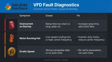
Overcurrent Fault on Startup
- Presents as: OC fault immediately or within seconds of starting
- Cause: Acceleration ramp time too short for load inertia, or a cable run over 100 feet creating excessive capacitive charging current
- Fix: Increase the acceleration ramp time in drive parameters. Add an output dV/dt filter between the drive and motor for long cable runs.
Motor Running Hot After Installation
- Presents as: Motor temperature significantly above normal, especially at lower speeds
- Cause: Below 30–40 Hz, standard TEFC motors lose cooling capacity as the shaft-mounted fan slows proportionally. A carrier frequency set too high also increases motor losses.
- Fix: Specify an inverter-duty motor with an independently powered cooling fan for sustained low-speed applications. Reduce carrier frequency to the minimum acceptable level for the load.
Erratic Speed or Unstable Motor Behavior
- Presents as: Speed fluctuates, hunts, or doesn't respond consistently to commands
- Cause: Incorrect motor nameplate data entered in drive parameters, or open-loop vector mode running without a completed auto-tune
- Fix: Re-verify all motor nameplate parameters in the drive settings. Run the auto-tune function with the motor unloaded and stationary to calibrate the drive's internal motor model.
Pro Tips for Installing a VFD on a 3-Phase Motor
**Separate signal wiring from power wiring** at every point inside the enclosure. Run them in separate conduits, or cross them at 90° where they must intersect. Even brief parallel routing of control cables alongside motor leads introduces noise that causes erratic behavior or nuisance faults.
Never megger a motor connected to a VFD — the high DC test voltage will damage the drive's output IGBTs. Per ABB's ACS580 installation documentation, always disconnect motor cables from the drive output terminals before any insulation resistance or voltage-withstand testing. A healthy motor reads >100 MΩ at 25°C — but only measure with the motor fully disconnected from the drive.
In multi-drive installations (water treatment facilities and manufacturing lines with multiple drives on the same bus) test each drive individually under load before enabling simultaneous operation. This isolates harmonic interactions and ground loop issues before they compound across the system.
Frequently Asked Questions
Can you use a VFD for a 3-phase motor?
Yes — VFDs are specifically designed for 3-phase AC induction motors and are the standard method for variable speed control in industrial applications. The drive must be matched to the motor's voltage, current, and frequency ratings for correct operation and protection.
When should you not use a VFD for a 3-phase motor?
Avoid VFDs with motors not rated for inverter duty, applications requiring full torque at near-zero speed without a vector drive and encoder feedback, and loads with critical resonant speed ranges. For pumps, use the drive's skip-frequency function to avoid continuous operation at those speeds.
Can a VFD convert single-phase input to three-phase output?
Most VFDs can accept single-phase input and produce three-phase output, which is useful when only single-phase power is available. Per ABB ACS550 documentation, the drive must be derated to 50% of its three-phase rating on single-phase input, so motor full-load current must not exceed that threshold.
How do I size a VFD for a 3-phase motor?
The VFD's output current rating must equal or exceed the motor's FLA from the nameplate. Factor in load type (constant vs. variable torque) and derating for ambient temperature above 45°C, altitude above 1,000 m, or elevated carrier frequency — always use the drive's published derating table.
What motor parameters do I need to program into the VFD during setup?
At minimum: rated voltage, rated current (FLA), rated frequency, rated RPM, and service factor. Incorrect nameplate data causes overload protection and vector control to operate on wrong assumptions, which can damage the motor without triggering a fault.
Do I need a line reactor or EMI filter with my VFD?
A line reactor is recommended for most industrial installations to reduce harmonic distortion and protect the drive from supply voltage transients — and required where IEEE 519 compliance is mandated. An output dV/dt or sine wave filter is recommended for motor cable runs over 100 feet or for motors sensitive to high dV/dt switching voltage.