Introduction
A tripped breaker during peak production isn't just an inconvenience — it's a financial event. According to Siemens' 2024 True Cost of Downtime report, the world's 500 largest companies lose approximately $1.4 trillion annually to unplanned downtime, equivalent to 11% of total revenues. Automotive manufacturers alone face costs of $2.3 million per hour when lines go dark.
Most of that exposure is preventable. Circuit protection is the deliberate design of safeguards that detect abnormal electrical conditions — overcurrent, overvoltage, short circuits, ground faults — and interrupt the circuit before damage reaches equipment, wiring, or people.
This guide covers the practical knowledge manufacturing environments need to act on that:
- Which electrical threats are specific to industrial floors — and why they behave differently than commercial settings
- The main protection device categories and how to select the right one for each application
- Compliance requirements under NEC, NFPA 70E, UL 508A, and IEEE 519
- How to build a layered protection strategy that reduces downtime without nuisance tripping
Key Takeaways
- Manufacturing facilities face overcurrent and overvoltage threats at higher energy levels than most commercial settings
- Motor inrush current at full-voltage start typically reaches 600% of full-load current, requiring correctly sized protection
- No single device handles all threat types; effective protection stacks primary, secondary, and component-level devices
- Device selection must account for interrupt rating, coordination, and enclosure type, not ampere rating alone
- VFDs and soft starters reduce inrush current, which simplifies upstream protection sizing and extends equipment life
What Makes Industrial Circuit Protection Different
The Intentional Weak Link
Circuit protection devices are engineered to fail first — predictably and safely. A $30 fuse protecting a $15,000 VFD is not a design compromise; it's the design. When abnormal conditions occur, the protection device sacrifices itself to preserve the equipment behind it.
Manufacturing environments face two fundamental failure modes:
- Overcurrent events — overloads, short circuits, earth faults caused by insulation failure or wiring damage
- Overvoltage events — transient spikes, motor switching surges, lightning entering through AC lines
Commercial and residential systems face these same failure modes — but manufacturing compounds them. Heavy motor loads, three-phase power, VFDs, continuous 24/7 schedules, and harsh physical environments push energy levels far higher. A missed fault doesn't just damage equipment; it creates fire and electrocution hazards.
NFPA reports 142 workers died from electrical exposure in 2023. Circuit protection under OSHA 29 CFR 1910 Subpart S and NEC Article 430 isn't optional — it's the baseline for personnel safety and regulatory compliance.
Why Manufacturing-Specific Threats Matter
Standard commercial protection is sized for linear loads with predictable current profiles. Industrial facilities run on a different set of conditions entirely:
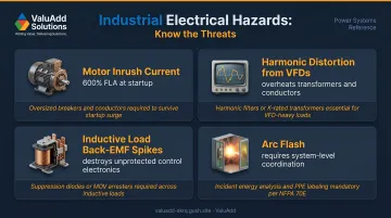
- Large motors draw inrush currents at every startup that can stress improperly sized protection devices
- VFDs generate harmonics that overheat transformers and neutral conductors over time
- Inductive loads like contactors, solenoids, and relay coils produce back-EMF spikes capable of destroying unprotected control electronics
- Arc flash events require system-level coordination well beyond basic overcurrent protection
Getting protection right means accounting for all of these — not just sizing devices for normal operating current and calling it done.
Common Electrical Threats on the Manufacturing Floor
Motor Inrush Current
When a motor starts across-the-line at full voltage, Rockwell Automation's data shows the current drawn from the power line is typically 600% of normal full-load current. For a 100-amp motor, that means 600 amps flowing through the circuit for several seconds at every start.
Protection devices must handle this without nuisance tripping, while still clearing genuine fault currents rapidly. Get that balance wrong and the consequences are immediate:
- Trip too sensitively and you halt production on every start
- Trip too slowly and a real fault destroys the motor or wiring
Harmonic Distortion from VFDs
Variable frequency drives and switching power supplies generate harmonic currents that don't appear on standard ammeters but cause real damage. Harmonics overheat transformers, neutral conductors, and cables — sometimes for months before anyone notices.
That slow degradation is exactly why IEEE 519-2022 exists — it's the active standard governing harmonic control in systems with nonlinear loads. Facilities with significant VFD populations need to address compliance through drive selection, input reactors, or active filters, not just overcurrent device sizing.
Transient Overvoltage
Three common sources on manufacturing floors:
- Motor switching surges — contactors opening under load generate voltage spikes that propagate through the system
- Back-EMF from inductive loads — relay coils, solenoids, and contactor coils release stored energy as fast transients when de-energized
- Utility-side lightning surges — enter through service entrances and can reach control panels and PLCs
These transients are fast — microseconds to milliseconds — and standard overcurrent devices don't respond quickly enough to stop them. Dedicated overvoltage protection is required.
Arc Flash
Arc flash is in a category of its own. An arcing fault releases tremendous energy as heat, light, and pressure — enough to cause severe burns or fatalities at considerable distances. Protection against arc flash requires:
- Devices rated for the available fault current at each point in the system
- Proper coordination so the closest device operates first
- Compliance with NFPA 70E and arc flash hazard analysis per IEEE 1584-2018
Arc flash analysis is not a device selection problem — it's a system design problem that requires engineering analysis.
Types of Circuit Protection Devices for Industrial Applications
Overcurrent Protection Devices
Industrial Fuses (HBC/Current-Limiting)
Current-limiting fuses operate in two modes: overload mode for sustained overcurrents, and current-limiting mode for high-magnitude short circuits, where they physically limit the let-through current before it reaches its peak value. This makes them highly reliable for protecting motors, semiconductors, and downstream equipment.
UL 248 requires a 200 kA interrupting rating for Class J, L, RK1, RK5, T, and CC fuses — well beyond what standard commercial fuses offer. The trade-off is that fuses are non-resettable; after operation, they must be replaced.
ValuAdd's RMS Modular Fuse Holders accommodate cylindrical fuses in 14×51mm and 22×58mm sizes, supporting HBC fuses up to 100 kA rms. Available configurations include:
- 1, 2, 3, 3+N, and 4-pole options to match panel layouts
- Built-in melt indicators for fast fault identification during production
Molded Case Circuit Breakers (MCCBs)
MCCBs handle both slow overloads (thermal trip) and instantaneous short circuits (magnetic trip) through a single device. They're resettable, which matters in facilities where recovery speed after a fault directly affects production output. UL evaluates MCCBs to UL 489.
For lower-current control circuits — 24 VDC logic supplies, PLC I/O power, HMI panels — miniature circuit breakers (MCBs) fill the same role at smaller current ratings. NOARK circuit breakers in ValuAdd's portfolio cover both MCB and MCCB applications for industrial power systems.
Residual Current Devices (RCDs/GFCIs)
RCDs detect ground faults — current flowing through an unintended path to earth — and interrupt the circuit before that current reaches dangerous levels for personnel. They're required under NEC Article 210 and OSHA 1910.304 for specific applications on the manufacturing floor.
ValuAdd's ACCULINE DCT-C residual current transformers provide Type A residual current measurement across a wide range of 36 to 630 A per phase, covering both single-phase and three-phase fault detection scenarios.
PTC/PPTC Thermistors
Positive Temperature Coefficient thermistors are resettable overcurrent devices suited for control circuits and electronics within control panels. When current exceeds their threshold, resistance increases sharply, limiting current without permanently opening the circuit.
When the fault clears and the device cools, it resets automatically. This makes PTCs well-suited for applications where frequent minor fault events occur and manual resetting would cause costly production delays.
Overcurrent devices address current-related faults, but voltage transients present an equally serious threat to industrial equipment. The following device types target overvoltage events specifically.
Overvoltage Protection Devices
Metal Oxide Varistors (MOVs)
MOVs are the standard workhorse for overvoltage protection on AC power lines. They clamp transient spikes by conducting heavily above their clamping voltage, absorbing surge energy before it reaches downstream equipment. Common placement points include motor control center inputs and VFD line-side panels.
One critical requirement: MOVs degrade with repeated surge events and can fail short-circuit. Always use them in series with a fuse so that a degraded MOV fails safely rather than creating a short circuit on the line.
Transient Voltage Suppression (TVS) Diodes
TVS diodes respond faster than MOVs and clamp more precisely, making them the right choice for protecting sensitive control electronics, PLCs, and sensor circuits. They handle lower energy levels than MOVs, so they belong on signal and control lines rather than main power conductors. For comprehensive protection, MOVs and TVS diodes are often used together: MOVs absorb bulk surge energy at the panel while TVS diodes provide fine-grained protection at the circuit board level.
Selecting the Right Circuit Protection
Interrupt Rating: Start Here
The single most dangerous selection error in industrial circuit protection is choosing a device with an interrupt rating below the available fault current at the installation point.
Available fault current (AFC) depends on the utility supply capacity and transformer impedance at the point of installation. A device that cannot interrupt available fault current will fail catastrophically — not safely — when a fault occurs. Every protection device installed must have an AIC (Ampere Interrupting Capacity) rating equal to or greater than the available fault current at that location. OSHA 1910.304 and NEC requirements both address this.
Determine AFC before specifying any device. Transformer nameplates and utility data are the starting point.
Coordination: Protecting the Right Branch
Proper coordination means the device closest to a fault operates first, isolating only the affected branch. Without it, a fault on a single motor branch can trip the main breaker for an entire production line — taking down far more than the problem circuit.
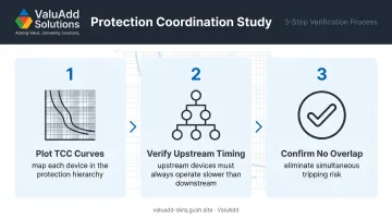
The tool for coordination analysis is the time-current curve (TCC) — a graphical representation of how quickly a device operates at different current levels. A coordination study typically involves three steps:
- Plot TCC curves for each device in the protection hierarchy
- Verify upstream devices always operate slower than downstream devices at every fault current level
- Confirm no curve overlap that would cause simultaneous tripping
Getting this right during design prevents the cascading shutdowns that make fault events far more costly than the fault itself.
Environment-Driven Enclosure Selection
| Environment | NEMA Rating | Typical Application |
|---|---|---|
| Standard indoor industrial | Type 12 | Most factory floors, control rooms |
| Washdown / food processing | Type 4X | Food & beverage, chemical processing |
| Outdoor with weather exposure | Type 3R | Rooftop or exterior panels |
ValuAdd's SW Series Washdown Drives carry UL Type 4X (IP66) rated polycarbonate enclosures rated for direct high-pressure washdown exposure. The RX4E and RX2E enclosed soft starters are available in NEMA 12 configurations for standard industrial settings.
Selecting the wrong enclosure class doesn't just risk ingress damage — it can void certifications and fail inspection.
Compliance and Standards for US Manufacturing
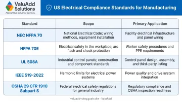
Five standards govern circuit protection in US manufacturing facilities:
- NEC (NFPA 70, 2023 edition) — the baseline for electrical design, wiring, and protection requirements, including motor branch circuits under Article 430
- NFPA 70E (2024 edition) — electrical safety in the workplace, covering arc flash hazard analysis and personal protective equipment requirements
- UL 508A — the standard for industrial control panels; devices and assemblies used in panels must meet listed component requirements
- IEEE 519-2022 — harmonic control limits for systems with nonlinear loads, directly applicable to VFD-heavy facilities
- OSHA 29 CFR 1910 Subpart S — federal electrical safety requirements covering wiring design, protection, and equipment safety
Each of these standards has a direct product-level counterpart. ValuAdd's certifications — UL Listed, IEEE 519 compliant, and NEMA Type 4X and 12 — map to these requirements specifically. The Benshaw H2 519/519P Series Clean Power Drives, for example, are engineered to meet IEEE 519-2014 Table 1 and Table 2 harmonic limits, with THDv below 8% and TDDi below 5%.
Using non-listed devices or incorrect enclosures creates liability exposure and fails inspection. The Authority Having Jurisdiction (AHJ) has final say on compliance at any given installation — which means involving the facility's electrical engineer, equipment supplier, and local inspector during design review — before procurement — is what separates a smooth inspection from a costly retrofit.
Building a Layered Circuit Protection Strategy
No single device handles every threat type. Effective protection stacks multiple layers:
- Service entrance level — surge protective devices and main overcurrent protection sized for available fault current
- MCC/panel level — MCCBs or HBC fuses with coordination to downstream devices; MOVs on VFD line-side panels
- Branch circuit level — individual breakers or fuses for each motor and load, with overload relays for sustained overcurrent
- Component level — MOVs and TVS diodes protecting PLCs, sensors, and control electronics from fast transients
How Motor Starting Solutions Reduce Protection Burden
Properly selected motor starters reduce the stress on upstream protection devices. VFDs limit inrush to approximately 100–150% of motor FLA at startup — compared to 600% for across-the-line starting. Soft starters provide controlled current ramp starting, with adjustable current-limit settings typically in the 150–400% FLA range.
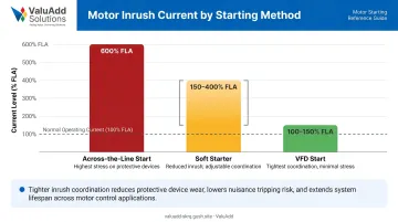
This matters for protection sizing: lower peak inrush means smaller margins between normal operating current and trip thresholds, enabling tighter coordination and reducing nuisance trips. ValuAdd's Benshaw soft starters and VFDs include built-in motor protection — overcurrent, ground fault, current imbalance, and voltage protection — eliminating the need for separate relay schemes for each function.
Preventive Maintenance: Protection Devices Degrade
Even well-specified protection devices lose effectiveness over time. MOVs degrade after repeated surge events. Thermal-magnetic breakers experience mechanical wear after repeated operations. Enclosure seals can fail, allowing contaminant ingress that compromises protection integrity.
ANSI/NETA MTS-2023 and NFPA 70B provide the maintenance testing frameworks for industrial electrical systems. A practical maintenance program includes:
- Periodic visual inspection of enclosures for ingress, corrosion, or physical damage
- Review of trip event logs to identify patterns before they become failures
- Testing of protection devices per NETA MTS intervals
- Post-surge inspection of MOVs in service entrance and panel-level surge protection
One maintenance manager at a water treatment facility using ValuAdd's MVRXE dual redundant soft starter system reported zero unplanned downtime since installation — crediting both the device's built-in redundancy and a structured quarterly inspection schedule.
Frequently Asked Questions
What is circuit protection?
Circuit protection is the deliberate inclusion of devices in an electrical system that detect and interrupt abnormal conditions — overcurrent, overvoltage, short circuits, or ground faults — before they damage equipment or endanger personnel. These devices are designed to fail predictably, sacrificing themselves to preserve the more expensive equipment downstream.
What are examples of circuit protection devices?
Common examples include fuses, circuit breakers (MCBs and MCCBs), residual current devices (RCDs/GFCIs), surge protective devices (MOVs and TVS diodes), overload relays, and PTC thermistors. Most industrial applications use several of these together, with each device targeting a specific threat type at a specific point in the system.
What is the difference between a fuse and a circuit breaker in manufacturing?
Fuses are one-time-use devices that clear faults very quickly — an advantage for motor and semiconductor protection. Circuit breakers are resettable and easier to restore after a fault, making them preferred where faster recovery is the priority. NEC Article 430 defines specific applications for each in motor branch circuit protection.
How do variable frequency drives affect circuit protection requirements?
VFDs generate harmonic distortion that can overheat wiring and transformers, requiring line-side protection rated for non-linear loads — IEEE 519-2022 compliance may mean adding input reactors or active filters. VFDs also dramatically reduce motor inrush current, which simplifies branch circuit protection sizing on the load side.
What NEMA enclosure rating do I need for circuit protection devices in a factory?
NEMA Type 12 covers most indoor industrial environments — protection from dust, dirt, and dripping liquids. NEMA Type 4X is required for washdown areas, food processing facilities, and corrosive environments. The correct rating must match the specific area classification, not just the general facility type.
How does poor circuit protection cause unplanned downtime?
Two failure modes: undersized or poorly coordinated protection causes nuisance tripping that halts production unnecessarily, while protection that's too slow allows equipment damage requiring extended repair. A formal coordination study resolves both problems by ensuring each device in the system responds in the right sequence at the right threshold.