Introduction
Wiring an automatic transfer switch is a technically demanding task that involves live high-voltage conductors, strict sequencing requirements, and both power and control wiring that must be completed correctly to prevent backfeed, equipment damage, or electrocution. OSHA and NIOSH records document multiple fatalities from improperly wired transfer switches, where backfeed into utility lines or failed isolation procedures created lethal conditions for workers.
This work should only be performed by licensed electricians or qualified industrial electrical technicians familiar with NEC Article 700/701/702 requirements and OSHA lockout/tagout procedures. Improper wiring creates multiple hazards:
- Backfeed into utility lines that can electrocute line workers
- Failed automatic transfer during an outage, leaving facilities de-energized
- Generator damage from incorrect control circuit connections
- Code violations that void insurance coverage
This guide covers the complete, correct wiring process for an ATS—from power connections and control circuit wiring to post-installation testing—following industrial best-practice standards and code requirements.
TL;DR
- ATS wiring requires licensed electricians or qualified industrial electrical technicians—not general tradespeople or DIYers
- The process covers two distinct circuits: power wiring (utility, generator, load) and control wiring (sensing, start/stop, neutral)
- De-energize both sources and apply OSHA 1910.147 lockout/tagout before any connections
- Use a UL 1008 listed, NEMA-rated ATS rated at or above the highest source's current draw
- Test by simulating an actual outage—verify transfer, generator start, and return-to-utility before energizing
Wiring Guide for an Automatic Transfer Switch
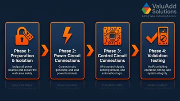
ATS wiring broadly consists of four phases: preparation and isolation, power circuit connections, control circuit connections, and validation testing.
Skipping or rushing any phase creates compounding safety risks—equipment damage, code violations, or electrocution hazards during commissioning or actual emergency operation.
Industrial ATS wiring for a 3-phase system typically takes a qualified electrician 4–8 hours depending on panel configuration, wire run distances, and whether a new generator feed conduit must be installed. This timeline assumes proper preparation, including verified conductor sizing and confirmed lockout/tagout procedures.
Prerequisites and Safety Considerations
Before beginning any wiring work, confirm these three prerequisites:
- Ampere rating: ATS rating must equal or exceed the highest current source—utility or generator
- Enclosure rating: NEMA Type 4X required for outdoor or industrial locations subject to moisture, washdown, or corrosive atmospheres
- Code compliance: UL 1008 listing for transfer switch equipment; NEC Articles 700/701/702 for emergency and standby systems
ValuAdd's ATS portfolio carries UL Listed and NEMA Type 4X certifications across multiple pole configurations—useful for integrators specifying equipment for outdoor or corrosive installations where both ratings are required.
Site readiness checklist:
- Sufficient panel space with conduit knock-outs for three conduit runs (utility feed, generator feed, load output)
- Dedicated conduit for control wiring separated from power cables per NEC 700.10(B)
- Conductor sizing verified against NEC Table 310.16 for required ampacity
- Terminal temperature rating confirmed (typically 75°C for equipment over 100A)
Non-negotiable safety requirements:
Do not proceed if utility power has not been confirmed off with a calibrated voltage tester, if the generator is running or capable of starting, or if lockout/tagout devices are not applied to both source breakers. OSHA 1910.333(b)(2) explicitly requires circuits be disconnected from all electric energy sources—interlocks or control circuits cannot substitute for physical lockout procedures.
Tools and Materials Required
Essential tools:
- Calibrated non-contact voltage tester (verify zero voltage before touching any wiring)
- Torque screwdriver or torque wrench for terminal torque spec compliance per NEC 110.14
- Wire stripper/crimper rated for conductor size
- Conduit bender and fish tape for installation runs
- Multimeter for continuity and voltage verification
- Insulated hand tools rated for working voltage (minimum 600V)
Key materials:
- THWN-2 copper conductors sized per NEC Table 310.16 for load current
- Metallic or liquid-tight conduit appropriate for environment
- Terminal lugs rated for conductor size and temperature
- Control wire (typically 14 AWG or per manufacturer specification for start command circuit)
- Shielded control cable if specified to prevent interference from power conductors
The ATS manufacturer's wiring diagram is a required reference document—terminal labeling varies by manufacturer and model. Never wire from memory or assumption.
How to Wire an Automatic Transfer Switch (Step-by-Step)
ATS wiring follows a strict sequence. Connecting the load output before both source inputs are terminated — or wiring control circuits before power circuits are confirmed correct — routinely causes commissioning failures and safety hazards during testing. Follow each step in order.
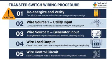
Step 1 — De-energize and verify
Open and apply lockout/tagout to the utility main breaker and the generator output breaker. Use a calibrated voltage tester to confirm zero voltage at all ATS input terminal locations before touching any wiring. Do not rely solely on breaker position—confirmed de-energization with a tester is mandatory per OSHA electrical safe work practices.
Step 2 — Wire Source 1 (utility) power connections
Run the utility feed conductors (L1, L2, L3, and Neutral for 4-pole units) through conduit to the ATS Source 1 input terminals, typically labeled "S1" or "Normal." Then complete the following:
- Strip conductor insulation to the length specified in the manufacturer diagram — too little prevents terminal contact; too much exposes live conductors
- Secure conductors to the correct terminals and torque to the manufacturer's specified value to prevent thermal loosening under load
Step 3 — Wire Source 2 (generator) power connections
Run the generator feed conductors through a separate conduit to the ATS Source 2 input terminals, labeled "S2" or "Emergency." Before energizing, verify two critical items:
- Conductor sizing: Match to the generator's rated output current, not just the ATS ampere rating — undersized conductors create voltage drop that prevents successful load transfer
- Phase rotation: Confirm rotation matches Source 1 using a phase rotation meter to prevent motor damage and controller lockout
Step 4 — Wire the load output
Connect the load output conductors from the ATS output terminals to the main distribution board or sub-panel being protected. On 4-pole ATS units, confirm the neutral is switched and that neutral conductors from Source 1 and Source 2 are not bonded together on the load side.
Critical neutral bonding rule: A 4-pole ATS creates a Separately Derived System (SDS) under NEC 250.30, requiring a dedicated system bonding jumper at the generator and a grounding electrode conductor. A 3-pole ATS with solid neutral is not an SDS—bonding the neutral at both the service and generator violates NEC 250.30 by creating parallel return paths that blind ground-fault protection.
Step 5 — Wire the control circuit
Two control circuit connections are required:
- Voltage sensing leads: Connect from the Source 1 input terminals to the ATS controller per the wiring diagram
- Generator start/stop command: A dry contact output from the ATS controller connects to the generator control panel's "remote start" terminals
Use shielded control cable if specified and route control wiring in separate conduit from power conductors to prevent induced voltage interference. Confirm polarity and terminal assignments against both the ATS and generator manufacturer diagrams — miswired start commands are a leading cause of failed generator starts during actual outages.
Post-Wiring Checks and Validation
Validation must occur in sequence: first check all connections visually and with continuity tests before energizing, then test each function progressively rather than energizing the full system at once. This staged approach isolates problems to specific circuits and prevents cascading failures.
Visual and torque check:
- Inspect all terminal connections for correct conductor assignment per wiring diagram
- Confirm no conductor insulation is pinched under terminals
- Verify all covers and live-part barriers are reinstalled
- Check that control and power wiring are routed in separate conduits or compartments per NEC 700.10(B)
- Re-torque all power terminals to manufacturer specification using calibrated torque driver
Functional test — utility to generator transfer:
With the generator running and stabilized, simulate a utility outage by opening the Source 1 breaker:
- Confirm the ATS controller detects loss of Source 1 voltage
- Verify the generator start command is issued (if generator was not already running)
- Confirm the controller waits the programmed transfer time delay before switching
- Verify the load transfers to Source 2 and all circuits are energized within normal voltage range
Functional test — return to utility and interlock verification:
Restore Source 1 and run through the retransfer sequence:
- Confirm the ATS waits the programmed retransfer delay before switching back to utility
- Verify the generator stop or cool-down command is issued after retransfer
- Confirm the mechanical or electrical interlock prevents both sources from connecting to the load simultaneously — this is a mandatory UL 1008 requirement, not optional
Record the following before closing out — this documentation supports compliance sign-off and establishes the baseline required by NFPA 110 Chapter 8:
- Measured transfer and retransfer times vs. programmed delays
- Voltage readings at load terminals for both sources
- Interlock verification result (pass/fail)
- Any anomalies observed and corrective actions taken
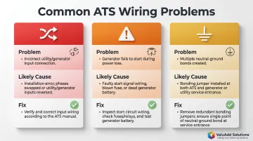
Common ATS Wiring Problems and Fixes
Source reversal (utility and generator inputs swapped)
Problem: ATS transfers to "generator" position during normal utility availability, or the control logic commands a generator start when utility is present and healthy.
Likely cause: Source 1 and Source 2 power conductors were connected to the wrong input terminals—a common error when terminals are unlabeled or the wiring diagram wasn't followed.
High-level fix: De-energize both sources, verify terminal labels against the manufacturer diagram, swap the conductor bundles to the correct terminals, re-torque all connections, and retest the transfer sequence from utility to generator and back.
Generator start command failure (ATS does not start generator on outage)
Problem: ATS detects loss of utility voltage but generator does not start; the load remains de-energized.
Likely cause: The dry contact start command wiring is missing, reversed in polarity, connected to the wrong terminals on the generator control panel, or the generator is in manual mode rather than remote auto start mode.
High-level fix:
- Confirm the generator is set to remote auto start mode before troubleshooting wiring
- Trace control wiring from the ATS start command output to the generator's remote start terminals and verify correct terminal connections
- Use a multimeter to confirm the dry contact closes during a simulated outage — continuity across the dry contact terminals confirms the start command is reaching the generator
Neutral bonding violation causing ground fault or nuisance tripping
Problem: Ground fault indicators trip, or nuisance breaker trips occur on the load side after ATS installation.
Likely cause: On a 4-pole ATS installation, the neutral conductor from the generator was bonded to the chassis ground at both the generator and the main panel, creating two neutral-to-ground bonds—a NEC violation in separately derived systems that creates parallel return paths.
High-level fix:
- Review NEC 250.30 requirements for separately derived systems
- Confirm only one neutral-to-ground bond exists: at the generator for a separately derived source (4-pole ATS), or at the main panel for a 3-pole ATS where the generator neutral is not switched
- Consult a licensed electrician if the bonding configuration is unclear
Pro Tips for Wiring an ATS Effectively
Keep these field-tested practices in mind before and during installation:
- Bench-test the control circuit first. Wire and verify all control logic with the ATS de-energized before connecting power conductors. Catching a miswired start command early prevents an uncontrolled generator start or failed transfer during commissioning.
- Match enclosure rating to the environment. In areas subject to moisture, washdown, or corrosive atmospheres, confirm the ATS enclosure carries a NEMA Type 4X or IP66/IP68 rating. A standard NEMA 1 or IP20-rated unit in these conditions leads to premature failure of internal contacts and control boards. ValuAdd stocks ATS components rated to NEMA Type 4X across the full enclosure, including control compartments.
- Document the as-built wiring configuration. Record conductor sizes, conduit routing, terminal assignments, control wire shielding method, and generator control panel terminal numbers. Store a copy inside the ATS enclosure and in the facility's electrical records—required for NEC-compliant installations and invaluable during future troubleshooting.
Conclusion
ATS wiring quality is the single biggest determinant of system reliability during an actual outage. A correctly wired ATS with validated transfer logic is a transparent safety device that operates flawlessly when utility power fails. A miswired one is a liability that creates electrocution risks, failed transfers, and code violations that compromise insurance coverage.
Treat this as a disciplined engineering task. Four non-negotiable steps apply to every installation:
- Follow the manufacturer's wiring diagram without shortcuts
- Apply lockout/tagout without exception before any work begins
- Complete all functional testing before placing the system in service
- Document the as-built configuration for future maintenance and inspections
A properly commissioned ATS should require no intervention during a real outage — that outcome depends entirely on the rigor applied during installation.
Frequently Asked Questions
What is ATS in electrical wiring?
An ATS (Automatic Transfer Switch) monitors the primary power source and automatically transfers connected loads to a backup generator when the primary fails, then retransfers when power is restored. This eliminates manual intervention during outages and prevents dangerous backfeeding into utility lines.
What is the difference between ATS and STS electrical?
An ATS switches between utility and generator backup using an open-transition (break-before-make) method, with a brief interruption during transfer. An STS uses solid-state devices to switch between two live utility feeds with near-instantaneous transfer times, making it the standard for dual-utility redundancy in critical facilities.
Can I wire an automatic transfer switch myself?
ATS wiring must be performed by a licensed electrician or qualified industrial electrical technician. It involves working with live high-voltage conductors and dual-source systems where wiring errors can cause backfeed, equipment damage, or code violations that void insurance coverage and create lethal hazards for utility workers.
What wires connect to an automatic transfer switch?
An ATS takes three conductor groups: Source 1 (utility input), Source 2 (generator input), and load output to the distribution panel. A separate control circuit carries voltage sensing leads and generator start/stop dry contacts, which must be routed in dedicated conduit away from power cables.
Do I need a 30 amp or 50 amp transfer switch?
The ATS ampere rating must equal or exceed the total current draw of all transferred circuits. A qualified electrician performs a load calculation to determine this value, then selects an appropriately rated switch per NEC Article 700/702 requirements. Undersizing causes overheating, nuisance tripping, and equipment failure.
How much does it cost to install an automatic transfer switch?
Residential ATS installations typically run $1,500–$3,000+ including labor and the switch unit. Industrial and commercial projects cost significantly more due to higher ampere ratings, 3-phase complexity, UL 1008 compliance requirements, NEMA 4X enclosures, and mandatory NETA acceptance testing for emergency systems.